Eureka AIR delivers breakthrough ideas for toughest innovation challenges, trusted by R&D personnel around the world.

Hydraulic control system for engineering machinery and excavator

A hydraulic control system and engineering machinery technology, applied in the field of hydraulic systems and excavators, can solve problems such as difficulty in application control of hydraulic equipment, and achieve the effects of being conducive to intelligent control, reducing potential safety hazards and facilitating operation

Active Publication Date: 2018-06-15
中联重科土方机械有限公司
View PDF5 Cites 1 Cited by
  • Summary
  • Abstract
  • Description
  • Claims
  • Application Information

AI Technical Summary

Problems solved by technology

[0003] The purpose of the present invention is to provide a hydraulic control system and an excavator for construction machinery, so as to solve the problem of difficulty in the application and control of hydraulic equipment on construction machinery

Method used


Image

  • Hydraulic control system for engineering machinery and excavator
  • Hydraulic control system for engineering machinery and excavator
  • Hydraulic control system for engineering machinery and excavator

Examples


Embodiment Construction

[0046] The core idea of ​​the present invention is to provide a hydraulic system of construction machinery, which can facilitate the use of external hydraulic equipment and can finely manage the external hydraulic equipment.

[0047] Specific embodiments of the present invention will be described in detail below in conjunction with the accompanying drawings. It should be understood that the specific embodiments described here are only used to illustrate and explain the present invention, and are not intended to limit the present invention.

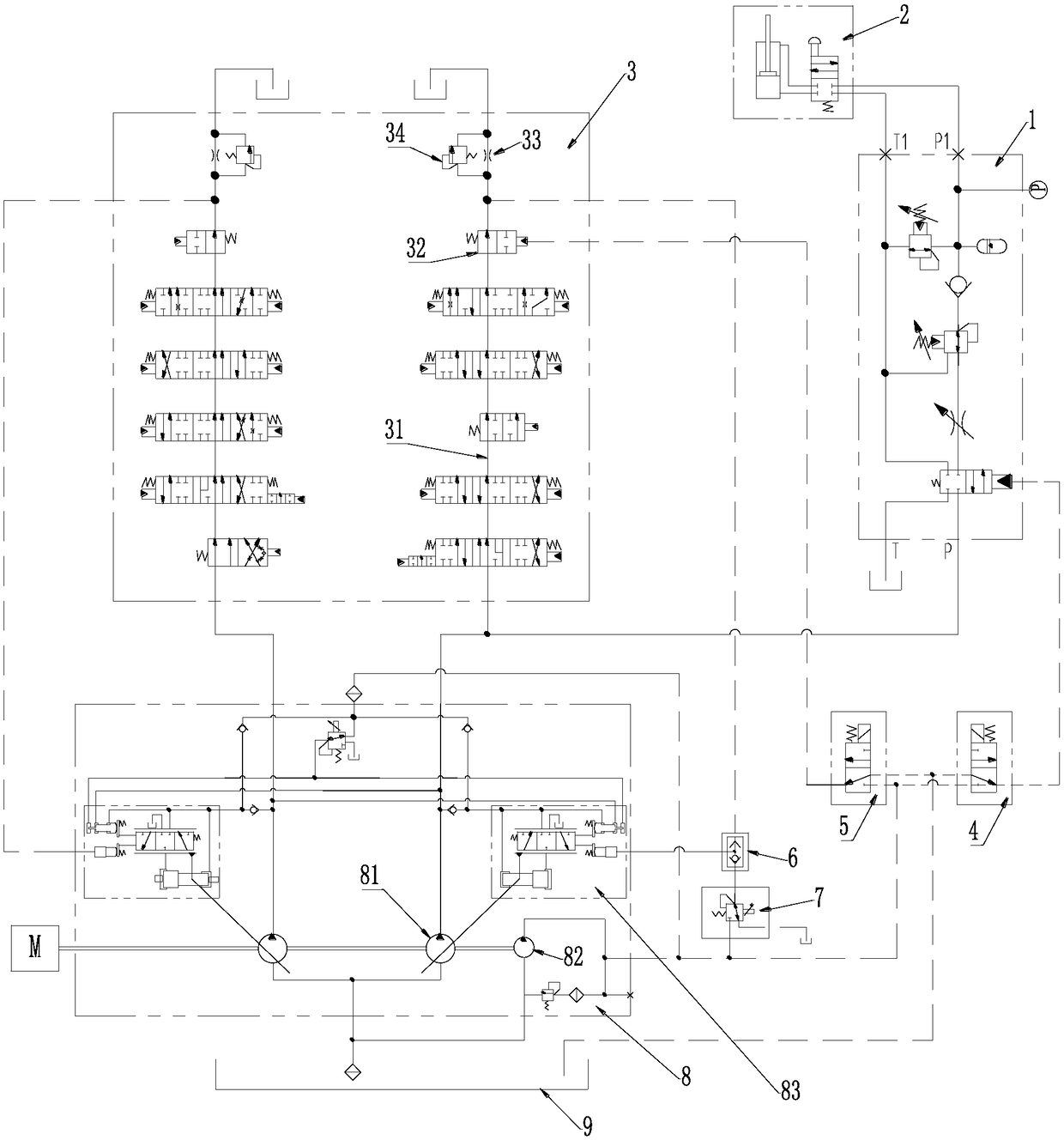
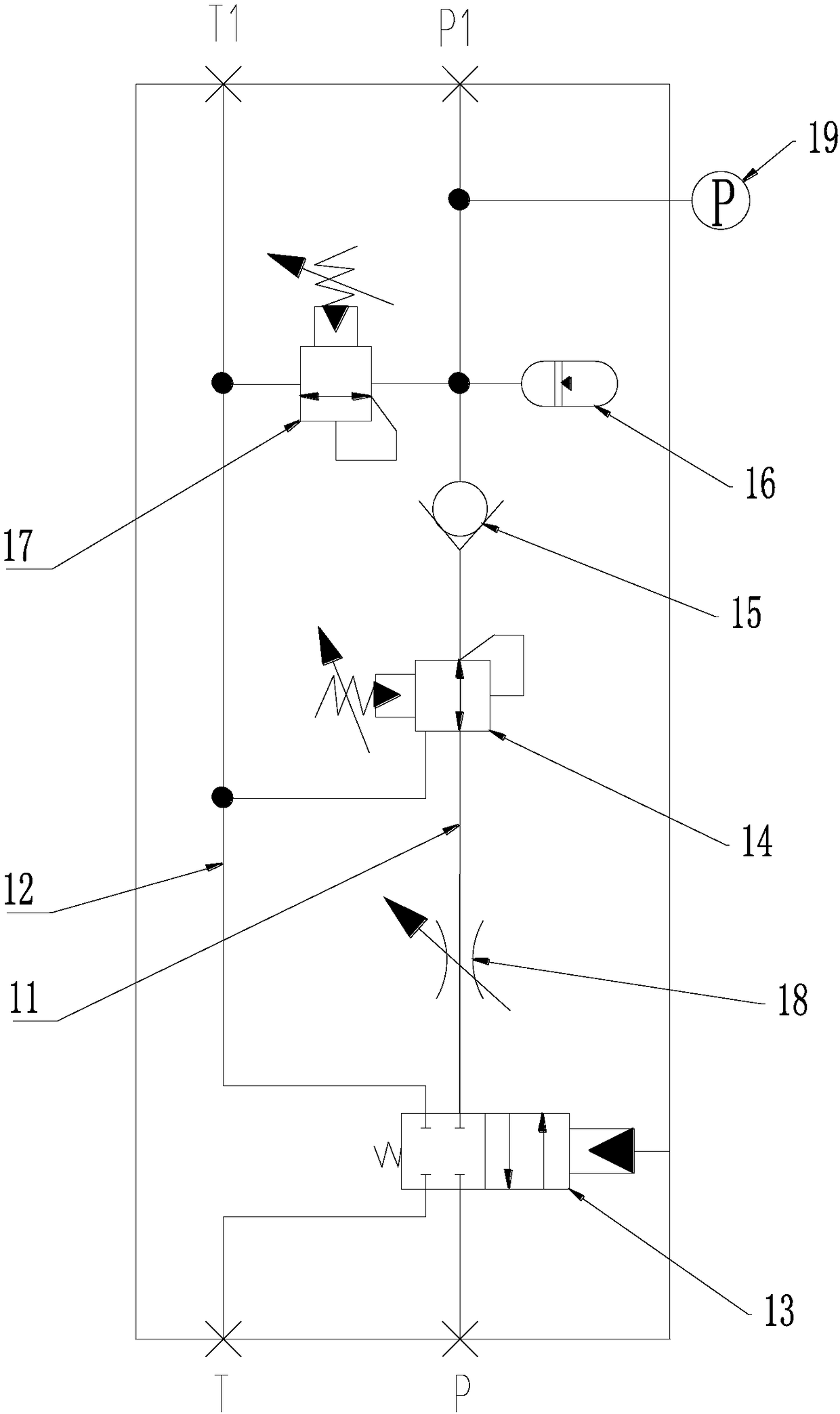
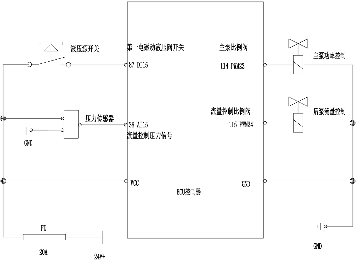
[0048] refer to figure 1 , which shows the hydraulic principle diagram of the hydraulic control system in this embodiment; image 3 It is a schematic diagram of the electrical system of the hydraulic control system. The hydraulic control system includes: a controller, a pump assembly 8, and an equipment control circuit 1, wherein the pump assembly 8 communicates with the equipment control circuit 1 to output hydraulic energy The hydrauli...


PUM


Abstract

The invention discloses a hydraulic system for engineering machinery and an excavator. The hydraulic control system comprises a controller, a pump assembly and an equipment control loop. The pump assembly communicates with the equipment control loop so as to output hydraulic oil with hydraulic energy to the equipment control loop. The equipment control loop comprises a connection pipe capable of being connected with hydraulic equipment, and the equipment control loop can perform speed regulation and / or pressure regulation on the hydraulic oil which is output by the pump assembly and provided with the hydraulic energy. The controller is connected with the equipment control loop, can obtain the pressure of the hydraulic oil in the connection pipe and control the output flow of the pump assembly according to the pressure of the hydraulic oil in the output pipe. By means of the technical scheme, the equipment control loop can perform speed regulation and / or pressure regulation on the hydraulic oil which is output by the pump assembly and provided with the hydraulic energy, fine operation of a self-controlled multifunctional small-sized hand-held hydraulic tool can be realized, intelligent control over the hydraulic system is facilitated, and thus fuel economy is realized.

Description

technical field [0001] The invention relates to the technical field of hydraulic control, in particular to a hydraulic system of construction machinery and an excavator. Background technique [0002] At present, on some large-scale hydraulic equipment, a spare oil port is usually reserved on the main control valve for installing hydraulic hammers, hydraulic shears and other operating tools. However, this kind of oil port is usually unable to provide power for various small hand-held hydraulic tools, and even if it can be applied, it is difficult to achieve fine control. Moreover, the action of the actuator of the hydraulic system is controlled by the operator in the cab, away from the workplace, which is inconvenient to operate and has potential safety hazards. On the other hand, the pressure and flow of the hydraulic system are greatly affected by other operating actions, and autonomous control cannot be realized The refined operation of multifunctional small hand-held hyd...

Claims


Application Information

Patent Timeline
Patent Type & Authority Applications(China)
IPC IPC(8): F15B1/02F15B11/00F15B13/02F15B21/08E02F9/22
CPCE02F9/22F15B1/02F15B11/00F15B13/02F15B21/08F15B2211/20576F15B2211/212
Inventor 张龙东荣张明珍梁恒张欣
Owner 中联重科土方机械有限公司
Why Eureka
Eureka Blog
Learn More