Frame hydraulic oil way

A hydraulic oil circuit and vehicle frame technology, applied in the field of vehicle frame hydraulic oil circuit, can solve problems such as low operating efficiency, unreasonable flow distribution of brake gear pump oil circuit and main pump oil circuit, uncoordinated actions, etc.

Pending Publication Date: 2018-06-15
FUJIAN XINYUAN HEAVY IND
View PDF0 Cites 2 Cited by
  • Summary
  • Abstract
  • Description
  • Claims
  • Application Information

AI Technical Summary

Problems solved by technology

The walking, slewing and digging actions of the excavator are all driven by the hydraulic oil circuit. However, the flow distribution of the brake gear pump oil circuit and the mai

Method used


Image

  • Frame hydraulic oil way
  • Frame hydraulic oil way
  • Frame hydraulic oil way

Examples


Embodiment

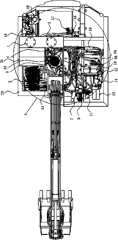
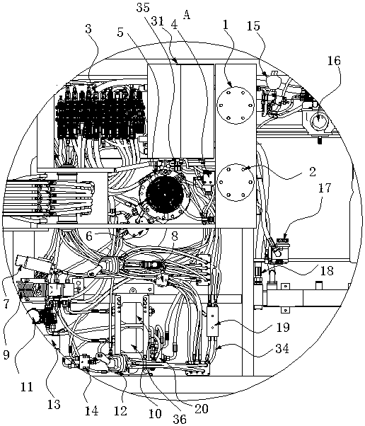
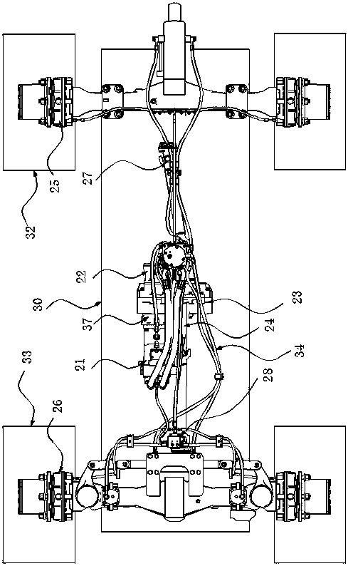
[0020] Frame hydraulic oil circuit, such as Figure 1 to Figure 4 As shown, including the hydraulic oil circuit of the upper frame and the hydraulic oil circuit of the lower frame.

[0021] The upper frame hydraulic oil circuit includes oil suction filter 1, oil return filter 2, oil tank 31 all arranged on upper frame 29, multi-way valve 3, high-speed shift valve 4, low-speed shift valve 35, and rotary motor 5 , central rotary joint 66, travel reversing valve 7, rotary shuttle valve 8, two-way brake valve 9, front diaphragm accumulator 10, rear diaphragm accumulator 10, hydraulic steering gear 11, parking brake control valve 12 , Fixture foot valve 13, double one-way valve 14, pilot oil source valve 15, main pump 16, brake gear pump 17, back pressure valve 18, oil collection block 19, liquid filling valve 20, pilot handle, left and right bridge Plate, accelerator control valve, accelerator pump.

[0022] Oil tank 31 is connected with oil suction filter 1 through oil pipe 34,...


PUM


Abstract

The invention relates to a hydraulic device, and discloses a frame hydraulic oil way. Oil suction filters are both connected with a brake gear pump and a main pump, and a liquid filling valve is connected with the brake gear pump and double-one-way valves. The double-one-way valves are correspondingly connected with a front diaphragm type accumulator, a rear diaphragm type accumulator and a parking brake control valve. The front diaphragm type accumulator and the rear diaphragm type accumulator are both connected with a double-way brake valve. A hydraulic steering gear and a pilot oil source valve are both connected with the main pump. A high speed shift valve, a low speed shift valve, a balance cylinder valve and an oil collecting block are all connected with the pilot oil source valve. Awalking reversing valve, a bulldozing valve and a rotary shuttle valve are all connected with the oil collecting block. The walking reversing valve, the bulldozing valve, the rotary shuttle valve andthe main pump are all connected with a multichannel valve. A central rotary joint is correspondingly connected with the double-way brake valve, the parking brake control valve, the high speed shift valve, the low speed shift valve, the balance cylinder valve, a hydraulic steering valve and the multichannel valve. The problems of unreasonable flow distribution of the oil way of the brake gear pumpand the oil way of the main pump are effectively solved.

Description

technical field [0001] The invention relates to hydraulic equipment, in particular to a frame hydraulic oil circuit. Background technique [0002] As an important construction machine, excavator plays a big role in production and construction. The walking, slewing and digging actions of the excavator are all driven by the hydraulic oil circuit. However, the flow distribution of the brake gear pump oil circuit and the main pump oil circuit of the traditional excavator is unreasonable, resulting in low operating efficiency and poor movement when leveling the ground and repairing slopes. coordination. Contents of the invention [0003] The object of the present invention is to provide a vehicle frame hydraulic oil circuit in which components in the oil circuit are arranged reasonably. [0004] In order to solve the above technical problems, the present invention is solved through the following technical solutions: [0005] The hydraulic oil circuit of the frame includes th...

Claims


Application Information

Patent Timeline
IPC IPC(8): F15B11/16F15B1/02E02F9/22
CPCF15B11/16E02F9/2264F15B1/02
Inventor 郑永忠
Owner FUJIAN XINYUAN HEAVY IND
Why Eureka
Try Eureka