Method for sampling and intersecting positioning of drone for air pollution emission monitoring
A technology of cross positioning and UAV, which is applied in the direction of measuring distance, measuring device, line-of-sight measurement, etc. It can solve the problem of difficult determination of high-altitude detection position, and achieve the effect of low manufacturing cost, easy operation and high accuracy
- Summary
- Abstract
- Description
- Claims
- Application Information
AI Technical Summary
Problems solved by technology
Method used
Image

Examples
Embodiment 1
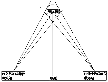
[0018] A sampling cross positioning method for air pollution emission monitoring by unmanned aerial vehicles, comprising the following steps:
[0019] The first step: determine the distance between the infrared thermal imager and the smoke source; the selection of the baseline length (the distance between the infrared thermal imager and the smoke source) is based on the principle of ensuring that the infrared thermal imager can see the complete smoke plume threshold contour line, generally can be At about 500 meters, the two observation points should be selected on both sides of the smoke axis as much as possible, and the optical axis of the thermal instrument lens should be perpendicular to the average wind direction as much as possible;
[0020] The second step is to determine the relative position of the drone and the flare plume; use two infrared thermal imagers to monitor the relative position of the drone and the flare plume, and observe the center of the drone and the pl...
Embodiment 2
[0025] A sampling cross positioning method for air pollution emission monitoring by unmanned aerial vehicles, comprising the following steps:
[0026] The first step: determine the distance between the infrared thermal imager and the smoke source; the selection of the baseline length (the distance between the infrared thermal imager and the smoke source) is based on the principle of ensuring that the infrared thermal imager can see the complete smoke plume threshold contour line, generally can be At about 500 meters, the two observation points should be selected on both sides of the smoke axis as much as possible, and the optical axis of the thermal instrument lens should be perpendicular to the average wind direction as much as possible;
[0027] The second step is to determine the relative position of the drone and the flare plume; use two infrared thermal imagers to monitor the relative position of the drone and the flare plume, and observe the center of the drone and the pl...
Embodiment 3
[0032] A sampling cross positioning method for air pollution emission monitoring by unmanned aerial vehicles, comprising the following steps:
[0033] The first step: determine the distance between the infrared thermal imager and the smoke source; the selection of the baseline length (the distance between the infrared thermal imager and the smoke source) is based on the principle of ensuring that the infrared thermal imager can see the complete smoke plume threshold contour line, generally can be At about 500 meters, the two observation points should be selected on both sides of the smoke axis as much as possible, and the optical axis of the thermal instrument lens should be perpendicular to the average wind direction as much as possible;
[0034] The second step is to determine the relative position of the drone and the flare plume; use two infrared thermal imagers to monitor the relative position of the drone and the flare plume, and observe the center of the drone and the pl...
PUM
 Abstract
Description
Claims
Application Information
 - R&D
- Intellectual Property
- Life Sciences
- Materials
- Tech Scout
- Unparalleled Data Quality
- Higher Quality Content
- 60% Fewer Hallucinations
Browse by: Latest US Patents, China's latest patents, Technical Efficacy Thesaurus, Application Domain, Technology Topic, Popular Technical Reports.
© 2025 PatSnap. All rights reserved.Legal|Privacy policy|Modern Slavery Act Transparency Statement|Sitemap|About US| Contact US: help@patsnap.com