
Intelligent safety relay and applied circuit thereof

A technology of safety relays and relays, which is applied in the direction of instruments, simulators, general control systems, etc., can solve the problems of large size, application limitations of safety relays, and high cost of forced-guided relays

Pending Publication Date: 2018-06-15
SHANGHAI CHENZHU INSTR +1
View PDF0 Cites 6 Cited by
  • Summary
  • Abstract
  • Description
  • Claims
  • Application Information

AI Technical Summary

Problems solved by technology

[0004] 1) Based on the technical scheme of the forced-guided relay, there is a guide rod between the normally closed contact and the normally open contact of the forced-guided relay, which makes the normally open contact and the normally closed contact never both closed, and the safety relay This feature can be used to effectively detect the closure of the output contacts to achieve the purpose of ensuring safety; however, due to the high cost and large size of the forced-guided relay, the cost of the safety relay using this technical solution is generally high , and difficult to miniaturize
[0005] 2) Based on the technical scheme of the semiconductor switch, the output of the semiconductor can be connected in series, and then the state of the semiconductor can be detected by using the voltage feedback. The semiconductor switch can make the volume smaller and the cost can be reduced, but due to the characteristics of the semiconductor switch The safety relay of the technical solution can only cut off the DC load, and the load must have a common point with the safety relay
This makes the application of safety relays using this technical solution limited, such as: AC loads, and isolation requirements

Method used


Image

  • Intelligent safety relay and applied circuit thereof
  • Intelligent safety relay and applied circuit thereof
  • Intelligent safety relay and applied circuit thereof

Examples


Embodiment Construction

[0027] The implementation of this patent application is described below through specific examples, and those skilled in the art can easily understand other advantages and effects of this patent application from the content disclosed in this specification. This patent application can also be implemented or applied through other different specific implementation modes, and various modifications or changes can be made to the details in this specification based on different viewpoints and applications without departing from the spirit of this patent application. It should be noted that, in the case of no conflict, the following embodiments and features in the embodiments can be combined with each other.

[0028] It should be noted that the diagrams provided in the following examples are only schematically illustrating the basic idea of ​​the patent application, and only the components related to the patent application are shown in the diagrams rather than the number of components i...


PUM


Abstract

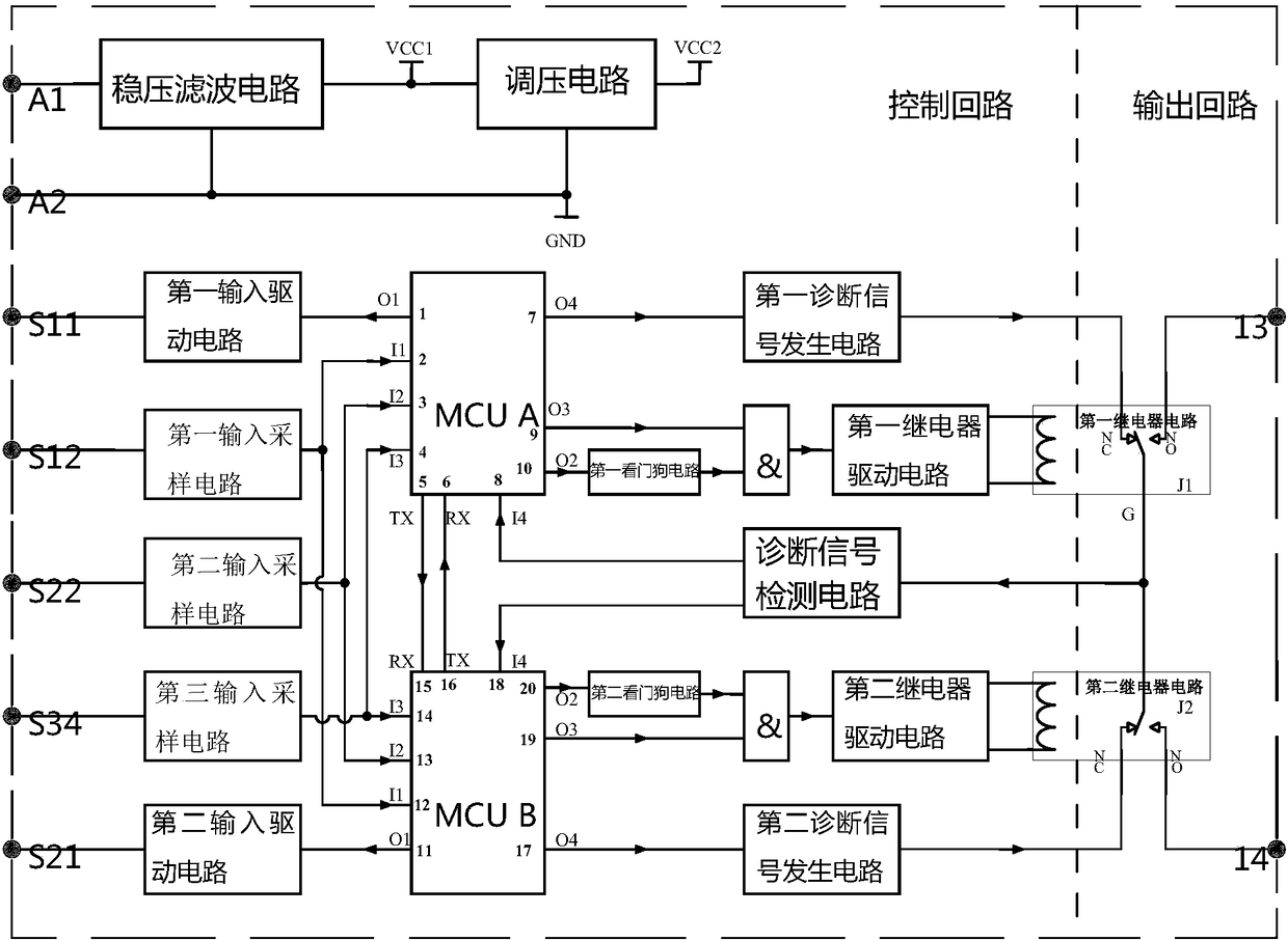
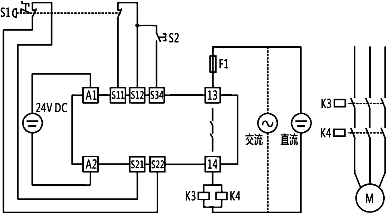
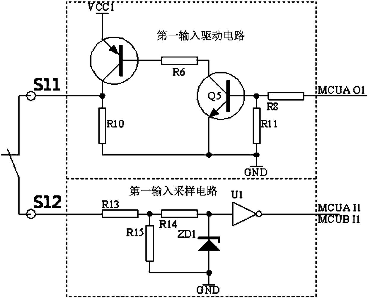
The invention applies for an intelligent safety relay and an applied circuit thereof. The intelligent safety relay is composed of a first processing chip MCU A, a second processing chip MCU B, first and second input driving circuits, first to third input sampling circuits, first and second diagnostic signal generating circuits, first and second logic circuits, a diagnostic signal detecting circuit, first and second relay driving circuits, and first and second relay circuits. The first processing chip MCU A and the second processing chip MCU B control connection or disconnection of contacts inthe first and second relay circuits automatically based on sampling on the input driving circuits by the input sampling circuits so as to control connection or disconnection of outputs; and the diagnostic signal generating circuits and the diagnostic signal detecting circuit detect various faults to realize connection or disconnection of outputs, so that intelligent and reliable cutting is realized. Moreover, on the basis of the intelligent plan, multiple kinds of safety functions or logic demands can be realized by configuration.

Description

technical field [0001] This patent application relates to the technical field of relays, in particular to an intelligent safety relay and its application circuit. Background technique [0002] The safety relay is a kind of safety control element, which is applied in the safety circuit and receives the signal of the safety element, such as emergency stop switch, safety light curtain, two-hand switch, safety mat. When these elements transmit dangerous signals to the safety relay, the safety relay Reliably cut off the power source and play a safe role. [0003] There are generally two technical solutions for traditional safety relays: [0004] 1) Based on the technical scheme of the forced-guided relay, there is a guide rod between the normally closed contact and the normally open contact of the forced-guided relay, which makes the normally open contact and the normally closed contact never both closed, and the safety relay This feature can be used to effectively detect the c...

Claims


Application Information

Patent Timeline
IPC IPC(8): G05B19/042
CPCG05B19/042
Inventor 陈小全周婷李兴磊宋光勇覃云丽
Owner SHANGHAI CHENZHU INSTR
Learn More