Finite element modeling system and method for bolt connection structure

A connection structure and finite element technology, applied in the field of finite element modeling, can solve the problems of simulation result error, inability to simulate bolt preload and parts contact behavior, etc., to achieve wide applicability, improve modeling and calculation efficiency, and solve calculation problems. large amount of effect

Inactive Publication Date: 2018-06-15
BEIJING INST OF RADIO MEASUREMENT
View PDF3 Cites 9 Cited by
  • Summary
  • Abstract
  • Description
  • Claims
  • Application Information

AI Technical Summary

Problems solved by technology

This simplified model cannot simulate the bolt preload and the contac

Method used


Image

  • Finite element modeling system and method for bolt connection structure
  • Finite element modeling system and method for bolt connection structure
  • Finite element modeling system and method for bolt connection structure

Examples


Embodiment Construction

[0027] In order to illustrate the present invention more clearly, the present invention will be further described below in conjunction with preferred embodiments and accompanying drawings. Similar parts in the figures are denoted by the same reference numerals. Those skilled in the art should understand that the content specifically described below is illustrative rather than restrictive, and should not limit the protection scope of the present invention.

[0028] Various cross-sectional views according to disclosed embodiments of the invention are shown in the drawings. The figures are not drawn to scale, with certain details exaggerated and possibly omitted for clarity of presentation. The shapes of various regions and layers shown in the figure, as well as their relative sizes and positional relationships are only exemplary, and may deviate due to manufacturing tolerances or technical limitations in practice, and those skilled in the art may Regions / layers with different ...


PUM


Abstract

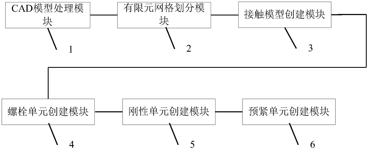
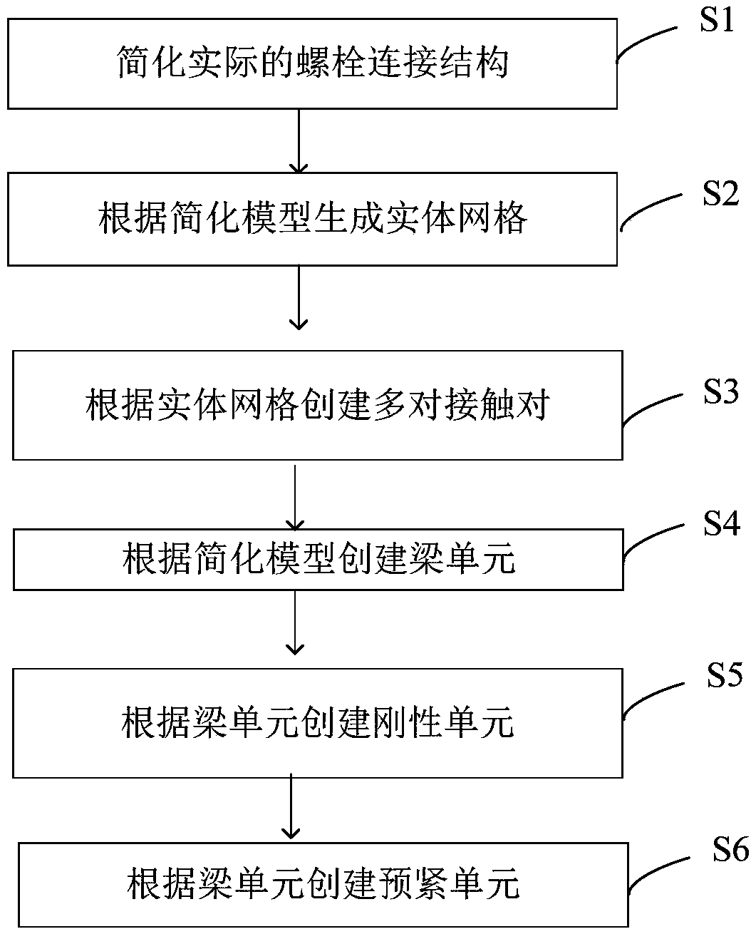
The invention discloses a finite element modeling system and method for a bolt connection structure. The finite element modeling system comprises a CAD model processing module, a finite element meshing module, a contact model creation module, a bolt element creation module, a rigid element creation module and a pretension element creation module. Compared to the prior art, the system and method provided by the invention have wide application; when key details are reserved, modeling and calculation efficiency is improved; and problems of fussy process and large calculation amount of detailed modeling and a problem of large error of simplified modeling are solved.

Description

technical field [0001] The present invention relates to finite element modeling. More specifically, it relates to a finite element modeling system and method for a bolted connection structure. Background technique [0002] The bolted connection structure is a detachable connection made of threaded parts. In the past, the finite element modeling method was detailed modeling or simplified modeling, that is, using solid elements to construct detailed bolted connection models, or using solid elements, plate shells, and rigid elements to establish Simplified bolted connection model. The main steps of detailed modeling are: divide the connected parts and bolts into solid elements; add surface-surface contact models on the contact surfaces of each part; insert preload force elements into the cross-section of the screw. This kind of modeling process is cumbersome and has a large amount of calculation, which is not conducive to dealing with complex problems. The main steps of simp...

Claims


Application Information

Patent Timeline
IPC IPC(8): G06F17/50
CPCG06F30/23G06F2119/06
Inventor 贺李平
Owner BEIJING INST OF RADIO MEASUREMENT
Why Eureka
Try Eureka