
Feed-through screw connection structure for generator stator core and installation method of feed-through screw connection structure

A generator stator and core-through screw technology, which is applied in the manufacture of stator/rotor body, magnetic circuit shape/style/structure, magnetic circuit static parts, etc., can solve the problem of few fixed support points, electrical accidents, and inability to effectively improve the screw natural frequency etc.

Active Publication Date: 2018-06-15
DONGFANG ELECTRIC MACHINERY
View PDF6 Cites 5 Cited by
  • Summary
  • Abstract
  • Description
  • Claims
  • Application Information

AI Technical Summary

Problems solved by technology

However, in the above technical solution, the through-core screw itself is not insulated, which may cause electrical accidents due to a short circuit between the screw and the iron core, and there are still few fixed support points formed on the length of the iron core, which cannot effectively increase the natural frequency of the screw.

Method used


Image

  • Feed-through screw connection structure for generator stator core and installation method of feed-through screw connection structure
  • Feed-through screw connection structure for generator stator core and installation method of feed-through screw connection structure
  • Feed-through screw connection structure for generator stator core and installation method of feed-through screw connection structure

Examples


Embodiment Construction

[0019] Below in conjunction with accompanying drawing, the present invention is described in detail.

[0020] In order to make the object, technical solution and advantages of the present invention clearer, the present invention will be further described in detail below in conjunction with the accompanying drawings and embodiments. It should be understood that the specific embodiments described here are only used to explain the present invention, not to limit the present invention.

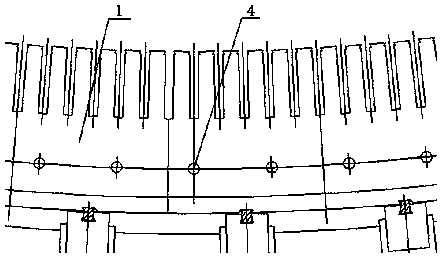
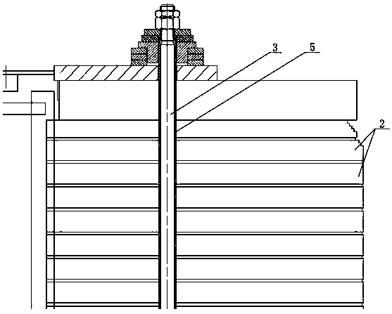
[0021] Such as Figure 2-5 As shown, a generator stator core through-core screw connection structure, the generator stator core 1 is formed by stacking and combining several iron core laminations 2, and the through-core screw 3 is composed of The hole 4 passes through and presses and fixes several stacked core laminations 2 together, and an insulating layer 5 made of a flexible material is provided on the outer periphery of the corresponding section of the through-hole screw 3 placed in the throu...


PUM


Abstract

The invention discloses a feed-through screw connection structure for a generator stator core. The generator stator core is formed by laminating a plurality of core laminations; a feed-through screw passes through a feed-through screw hole of the generator stator core and the plurality of laminated core laminations are pressed and fixed together; an insulating layer prepared from a flexible material is arranged on the periphery of a corresponding segment, in the feed-through screw hole, of the feed-through screw; the diameter of the corresponding segment, provided with the insulating layer, ofthe feed-through screw is not smaller than the aperture of the feed-through screw hole; the feed-through screw is put into the feed-through screw hole; and then the periphery of the insulating layerof the feed-through screw is in contact with a hole wall of the feed-through screw hole. On the basis of an existing feed-through screw structure, the insulating layer prepared from the flexible material is arranged on the periphery of the feed-through screw, and the insulating layer is in contact with the hole wall of the feed-through screw hole, so that multi-point contact of the feed-through screw and the core is achieved to improve the inherent frequency of the screw, the inherent frequency is far away from the vibration frequency of the core, resonance is avoided, and meanwhile, the feed-through screw connection structure plays a screw insulating role.

Description

technical field [0001] The invention belongs to the technical field of generators, and in particular relates to a connecting structure of a core-through screw of a generator stator core and an installation method thereof. Background technique [0002] Such as figure 1 As shown, the connection structure of the existing generator stator core is fixed by the through-hole screw. Between the through-hole screw and the through-hole screw hole, there is generally a gap of 0.75-1mm on one side to facilitate the penetration of the screw. , but this gap makes only the upper and lower ends of the core-through screw fixed, and the middle is in a suspended working state, and the overall length of the core-through screw is relatively long, resulting in the lack of effective support for the iron core in the suspended part of the screw, which is likely to cause large damage when the unit is running. Vibration or resonance, the unit runs loudly, and does not have insulation performance. ...

Claims


Application Information

Patent Timeline
Patent Type & Authority Applications(China)
IPC IPC(8): H02K1/18H02K15/02
CPCH02K1/18H02K15/02
Inventor 贺建华向春德郑小康钱昌燕梁宇强黄智欣徐兰坤
Owner DONGFANG ELECTRIC MACHINERY
Learn More