Textile winding roller

A technology for winding rollers and textile machines, which is used in the transportation of filamentous materials, thin material processing, transportation and packaging, etc., can solve the problem of insufficient uniformity and compactness of winding, reduced working efficiency of textile machines, and winding of winding rollers. The problem of small quantity, etc., achieves the effect of novel design, avoiding frequent replacement of winding rollers, and fast and uniform winding.

Active Publication Date: 2018-06-19
安徽海洋网业有限公司
View PDF8 Cites 20 Cited by
  • Summary
  • Abstract
  • Description
  • Claims
  • Application Information

AI Technical Summary

Problems solved by technology

[0004] The purpose of the present invention is to solve the problem that the structure of the winding roller in the prior art is simple, difficult to install and disassemble, the winding is not uniform and tight enough, the amount of winding of the winding roller is small, and the winding roller needs to be replaced frequently, resulting in the work efficiency of the textile machine. reduce the disadvantages of the traditional existence, and propose a kind of winding roller for textile

Method used


Image

  • Textile winding roller
  • Textile winding roller
  • Textile winding roller

Examples


Embodiment 1

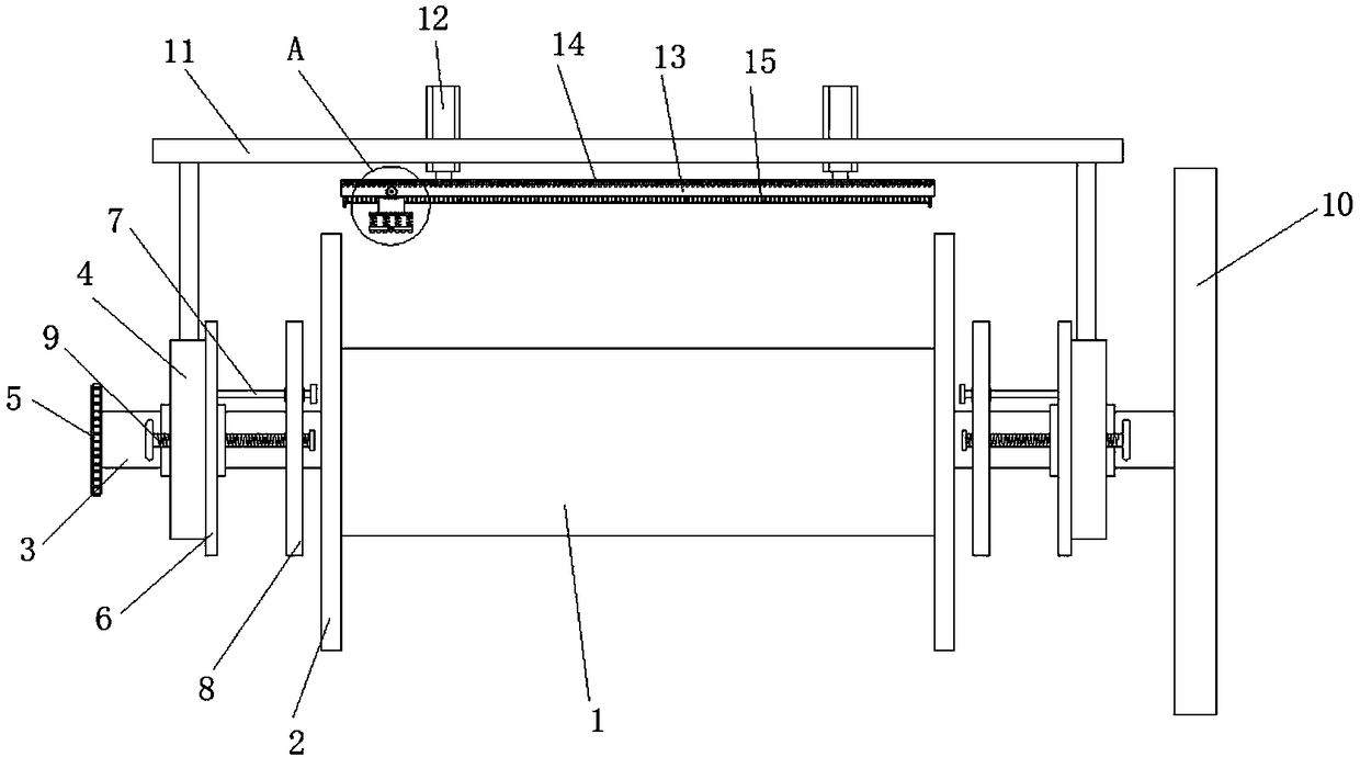
[0024] refer to figure 1 and 2 , a winding roller for textile use, comprising a winding roller main body 1, both ends of the winding roller main body 1 are provided with a limiting plate 2, and a supporting shaft is fixedly connected to the center of the circle on the side where the two limiting plates 2 are far away from each other 3, one end of a support shaft 3 away from the limit plate 2 is fixedly equipped with a transmission gear 5, and the transmission gear 5 meshes with the output shaft of the drive motor on the textile machine, and the other support shaft 3 is far away from the end of the limit plate 2. One end is fixedly connected with a support plate 10, the support plate 10 and the limit plate 2 are parallel to each other, the middle sections of the two support shafts 3 are equipped with a support block 4 through bearings, the support block 4 is a disc-shaped structure, and is provided with a connecting mechanism, The winding roller main body 1 is installed on the...

Embodiment 2

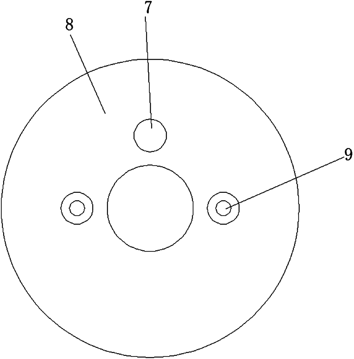
[0027] refer to figure 1 , 3 and 4, the connection mechanism includes a fixed ring plate 6, the fixed ring plate 6 is arranged on the side of the support block 4 close to the limit plate 2, and the side of the fixed ring plate 6 away from the support block 4 is provided with a guide near the support shaft 3 Slide bar 7, guide slide bar 7 and fixed annular plate 6 vertical settings, and one end away from fixed annular plate 6 is provided with circular spacer plate, movable annular plate 8 is installed on guide slide bar 7, fixed annular plate 6 and The sides of the movable annular plates 8 that are close to each other are all provided with anti-slip rubber pads, and the anti-slip rubber pads are provided with anti-slip protrusions, and the position of the support block 4 near the bearing is symmetrically provided with threaded holes that run through itself and the fixed annular plate 6 about the center of the circle, and Fastening bolts 9 are movably connected in the threaded ...

Embodiment 3

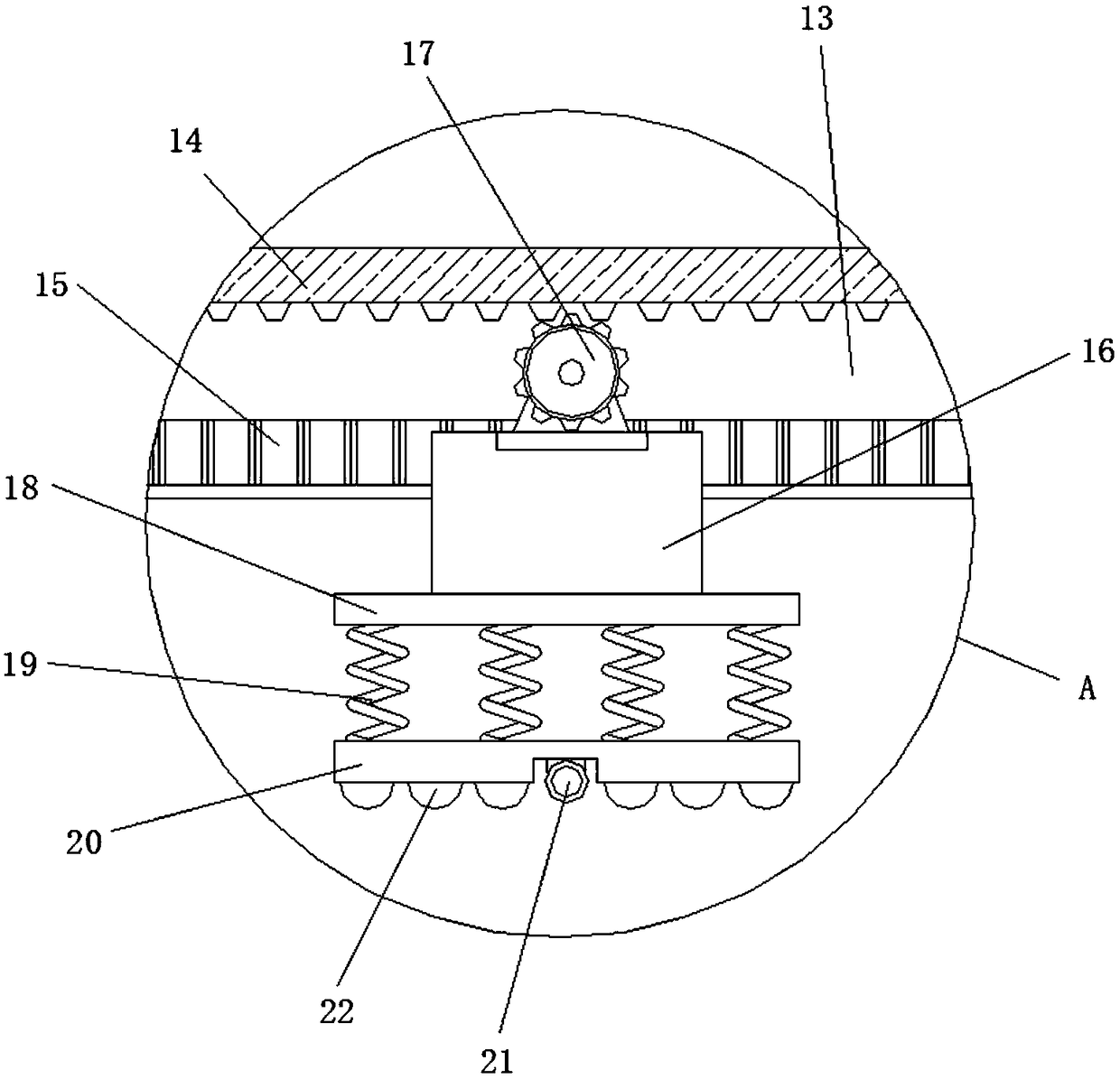
[0030] refer to figure 2, the wire management device includes a mobile base 16, and the mobile base 16 is movably installed on the moving track 15, and both ends of the moving track 15 are provided with limit blocks, and the driving motor 17 is installed on the moving base 16, and the output shaft of the driving motor 17 A drive gear is installed, the drive gear meshes with the transmission rack 14, the side of the mobile base 16 close to the winding roller main body 1 is provided with a mounting plate 18, and the side of the mounting plate 18 close to the winding roll main body 1 is equidistantly provided with compression springs 19. The end of the compression spring 19 away from the mounting plate 18 is fixedly connected to the leveling plate 20. A groove is provided in the middle of the side of the leveling plate 20 close to the winding roller body 1, and a wire management tube 21 is arranged in the groove. The wire management tube Rolling beads 22 are equidistantly arrang...


PUM


Abstract

The invention discloses a textile winding roller comprising a winding roller body. The two ends of the winding roller body are both provided with limiting plates. The circle centers of the sides, faraway from each other, of the two limiting plates are each fixedly connected with one end of a supporting shaft. The end, far away from the corresponding limiting plate, of one supporting shaft is fixedly provided with a transmission gear. The transmission gear is meshed with an output shaft of a drive motor on a spinning machine. The end, far away from the limiting plate, of the other supporting shaft is fixedly connected with a supporting disk. The supporting disk is parallel to the corresponding limiting plate. The middle sections of the two supporting shafts are provided with supporting blocks through bearings. The textile winding roller is novel in design and convenient and rapid to use, the winding roller body is fixedly installed on a machine frame of the spinning machine through a connection mechanism, installation is firm, and disassembly is convenient and rapid; and a yarn carding device can tightly press the yarn during carding, so that the winding amount of a single windingroller body is improved, frequent replacement of the winding roller is avoided, and the work efficiency of the spinning machine is improved.

Description

technical field [0001] The invention relates to the technical field of textile machines, in particular to a winding roller for textile use. Background technique [0002] Textile machines are also called textile machines, looms, cotton spinning machines, etc. The ancient textile machines were looms driven by human power. Textile machine is exactly the full name of the tool that processes thread, silk, hemp and other raw materials into silk thread and then weaves it into cloth. Such as spinning pendants, spinning wheels, spindles, pedal looms, modern mechanical looms, modern numerically controlled automatic looms, etc. The development of ancient and modern textile processes and equipment is designed in response to textile raw materials. Therefore, raw materials play an important role in textile technology. The fibers used for weaving in various countries in the ancient world are all natural fibers, generally three short fibers (wool, hemp, and cotton). [0003] Winding roll...

Claims


Application Information

Patent Timeline
Patent Type & Authority Applications(China)
IPC IPC(8): B65H57/28B65H67/04B65H54/38B65H54/553B65H54/70
CPCB65H54/385B65H54/553B65H54/70B65H57/28B65H67/0411B65H67/0417B65H2701/31
Inventor 计振南
Owner 安徽海洋网业有限公司
Why Eureka
Try Eureka