Reinforce structure of prefabricated beam-column compression joint and construction method thereof

A technology for strengthening structures and prefabricated columns, applied in building structures, buildings, etc., can solve the problems of high concrete repair cost and easy slurry leakage, and achieve the effects of reducing construction support modulus, improving seismic performance and fast construction speed.

Pending Publication Date: 2018-06-19
CHINA STATE CONSTRUCTION ENGINEERING CORPORATION
View PDF6 Cites 5 Cited by
  • Summary
  • Abstract
  • Description
  • Claims
  • Application Information

AI Technical Summary

Problems solved by technology

[0006] The purpose of the present invention is to provide a prefabricated beam-column crimping joint reinforcement structure and its construction method, to solve the technical problem that the g

Method used


Image

  • Reinforce structure of prefabricated beam-column compression joint and construction method thereof
  • Reinforce structure of prefabricated beam-column compression joint and construction method thereof
  • Reinforce structure of prefabricated beam-column compression joint and construction method thereof

Examples


Embodiment 1

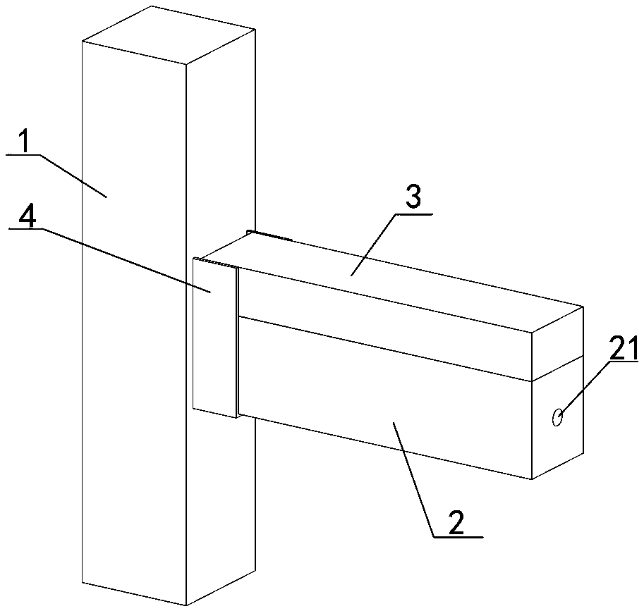
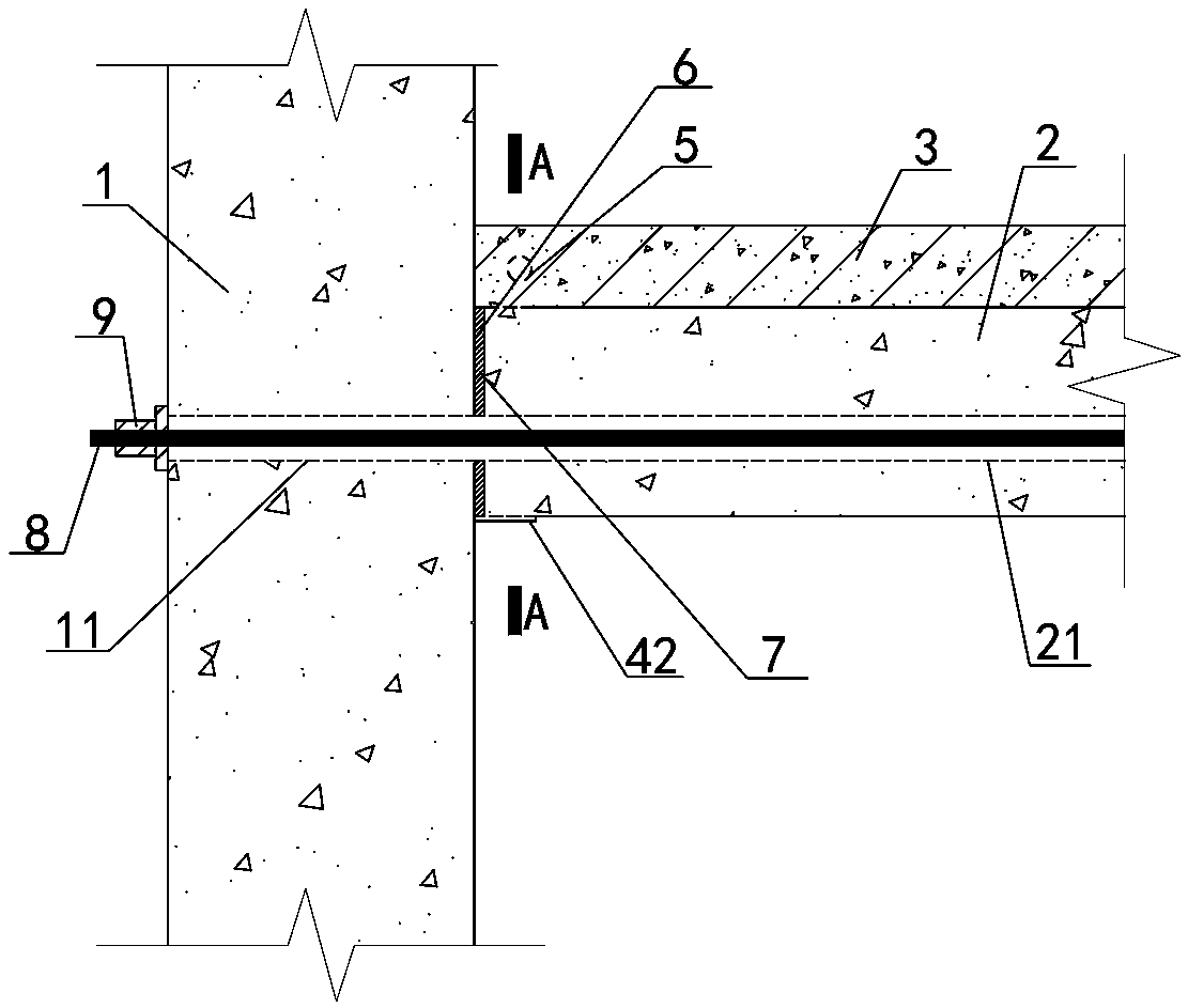
[0048] Embodiment one sees Figure 1-4 As shown, a prefabricated beam-column crimping joint reinforcement structure includes a connected concrete prefabricated column 1 and a concrete composite beam, and the composite beam includes a prefabricated lower part 2 and a cast-in-place upper part 3, and the The end of the composite beam is covered with a node strengthening device, and the node strengthening device includes a U-shaped bracket 4 and an anchor rod 5 .

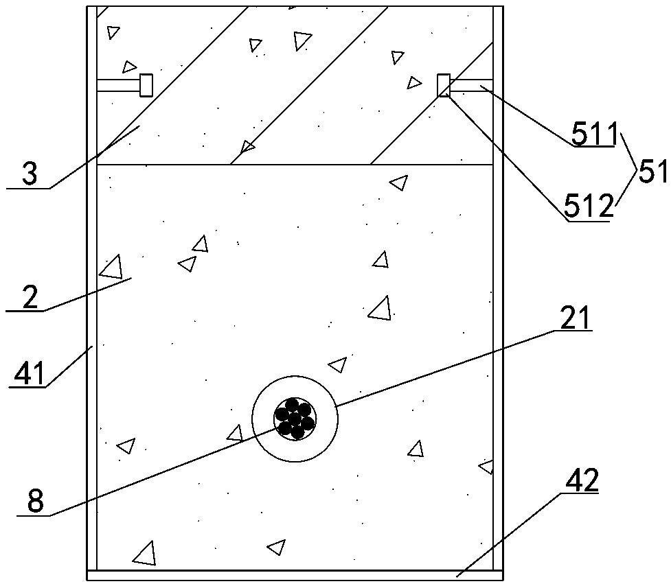
[0049] The U-shaped bracket includes two parallel vertical side plates 41 and a horizontal bottom plate 42 , and the two ends of the horizontal bottom plate 42 are respectively fixedly connected with the bottom of the vertical side plates 41 .

[0050]The upper side of the horizontal bottom plate 42 is close to the bottom side of the composite beam, the inner side of the vertical side plate 41 is close to the two outer sides of the width direction of the composite beam, and the front end surface of the vertical side pla...

Embodiment 2

[0065] Embodiment two see Figure 1-2 , 5-6, different from Embodiment 1, the anchor rod 5 is a screw rod 52, and the screw rod 52 is linear, and the length of the screw rod 52 is greater than the setting distance between the vertical side plates 41, and the screw rod 52 Both ends of the screw rod 52 are provided with external threads 521, and the corresponding positions of the two vertical side plates 41 are provided with opposite side plate screw holes 411, and the two ends of the screw rod 52 pass through the side plate screw holes 411 respectively, and the two external threads of the screw rod 52 521 are threadedly connected with two nuts 53 respectively, and the two ends of the screw rod 52 are also sleeved with two backing plates 10 with a backing plate screw hole in the center and close to the outer side of the vertical side plate 41, and the two nuts 53 are respectively tightened. Be fixed to the outer sides of the two backing plates 10.

[0066] The diameter of the s...


PUM

PropertyMeasurementUnit
Widthaaaaaaaaaa
Thicknessaaaaaaaaaa
Widthaaaaaaaaaa

Abstract

The invention relates to a reinforce structure of a prefabricated beam-column compression joint and a construction method thereof. The reinforce structure of the prefabricated beam-column compressionjoint comprises a prefabricated column and a laminated beam, wherein the laminated beam comprises a prefabricated lower portion and a cast-in-place upper portion; the end portion of the laminated beamat a beam-column connecting joint is wrapped with a joint strengthening device; the joint strengthening device comprises a U-shaped support piece and an anchor rod; a gap is reserved between the prefabricated column and the prefabricated lower portion; the U-shaped support piece is used as a template in the gap to be filled with grouting materials; and the anchor rod is integrally anchored into the cast-in-place upper portion. According to the reinforce structure of the prefabricated beam-column compression joint and the construction method, the amount of on-site construction modulus is reduced and the construction speed is high; the concrete bearing capacity of the bottom of the beam end can be effectively improved by creating an additional restraining effect on a beam end concrete, andtherefore the seismic performance of the joint is improved.

Description

technical field [0001] The invention belongs to the field of prefabricated node installation, in particular to a reinforced structure of a prefabricated concrete beam-column crimped node and a construction method thereof. Background technique [0002] Prefabricated concrete frame structure is a construction method with fast construction speed, good economic and environmental benefits. From the perspective of force and construction convenience, the node structure of the prefabricated structure is the key influencing factor. At present, the beam-column joints of the prefabricated frame structure mostly adopt the method of cast-in-place in the joint area. This method needs to deal with the avoidance of beam-column reinforcement in the joint area, the workload of wet work is large, and the construction efficiency is not high. Another crimping method of beam-column joints can better avoid the above shortcomings. In its structure, the beam-column joints are crimped together by pr...

Claims


Application Information

Patent Timeline
IPC IPC(8): E04B1/20E04B1/21E04B1/22
CPCE04B1/20E04B1/215E04B1/22
Inventor 郭海山李黎明刘康王冬雁齐虎李明田力达耿娇范昕谢永兰李桐
Owner CHINA STATE CONSTRUCTION ENGINEERING CORPORATION
Why Eureka
Try Eureka