

Beam end weakened replacement type steel frame beam shock proof node
A steel frame and joint technology, applied in the field of steel frame beam-column joints, can solve the problems of potential safety hazards, lower static stiffness of components, weakened flanges, etc., and achieve the effects of simple structure, good seismic effect and low material cost
- Summary
- Abstract
- Description
- Claims
- Application Information
AI Technical Summary
Problems solved by technology
Method used
Image

Examples
Embodiment 1
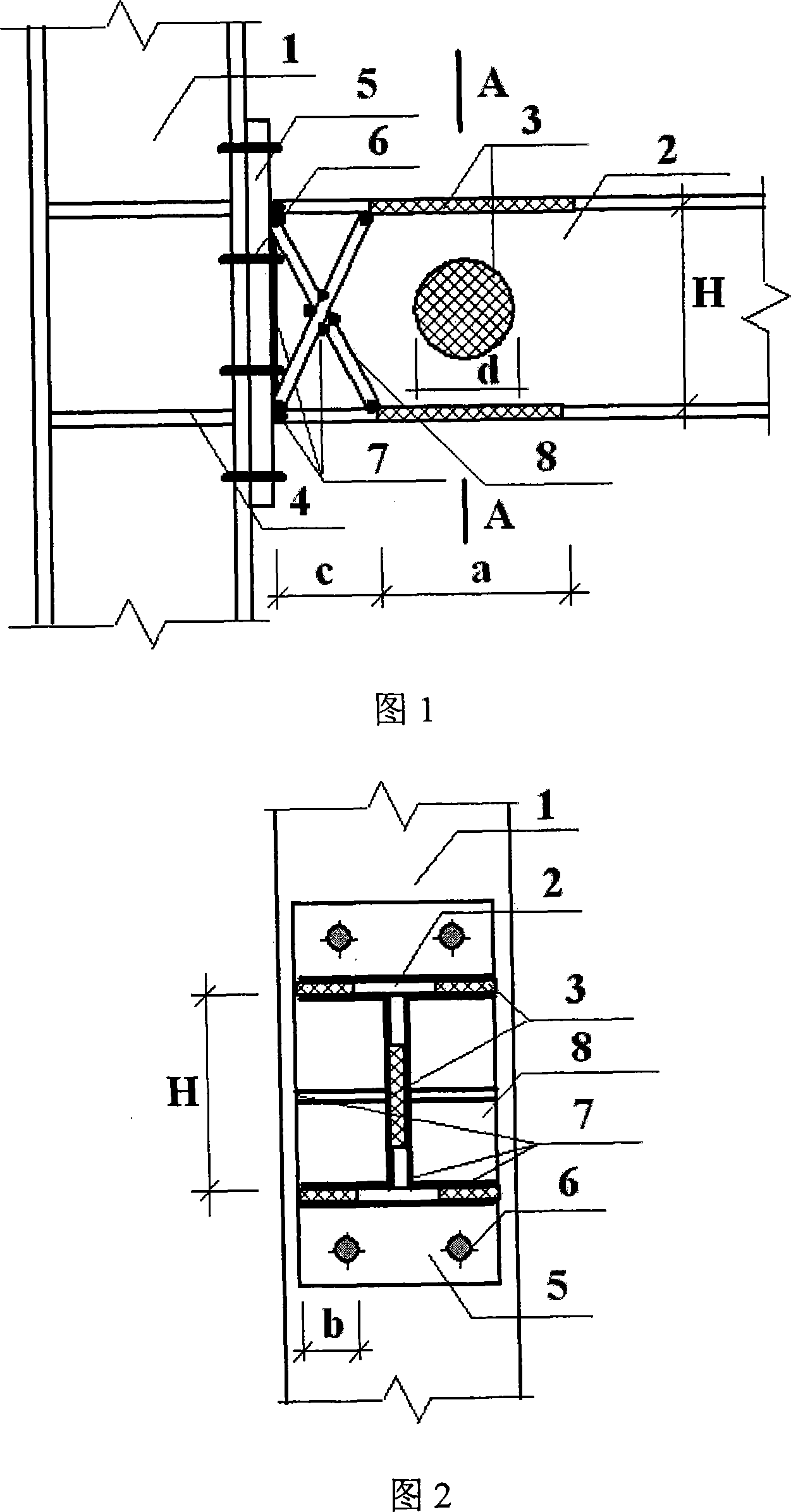
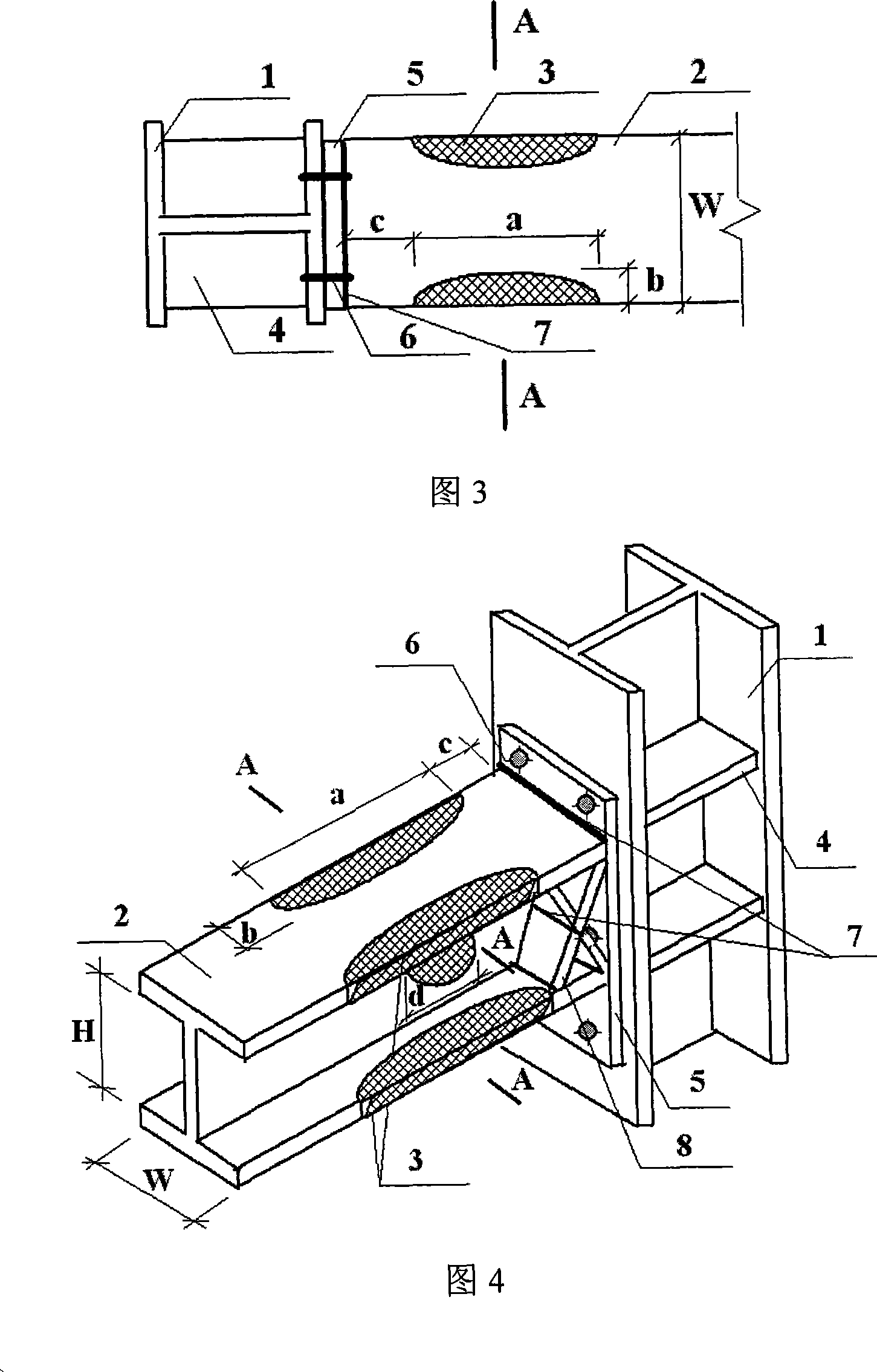
[0026] During the specific implementation, if the original beam-column joints are to be transformed, the bottom of the steel beam needs to be fixed with scaffolding or supports before operation. If it is in the construction of beams and columns, steel columns or concrete filled steel tube columns 1, steel beams with flanges and webs 2, column flange stiffeners 4, and end plates 5 can be assembled into a rigid structure with bolts 6 and welds 7. Or semi-rigidly connect the node and then cut and weld the beam end, or first cut and weld the steel beam 2 with the flange and the web and then form the node with other components.
[0027] On the steel beam near the column end, cut the upper and lower flanges symmetrically to the web along the longitudinal direction of the beam, as shown in Figure 1 and Figure 3, to ensure that the curve shape of the cut part of the flange on either side is a symmetrical quadratic parabola , and the vertical distance between the vertex of the parabola...
Embodiment 2
[0032] The structure of this embodiment is exactly the same as that of Embodiment 1, except that the distance c between the cutting point closest to the end plate 5 and the end plate is 45% of the width W of the steel beam; the upper and lower flanges are symmetrical to the web The cutting length a of the left and right sides is 80% of the height H of the steel beam; the maximum width b of the cutting part of the flange on one side is 30% of the width W of the steel beam, and the cutting area of the web part accounts for the largest web cutting along the longitudinal direction of the steel beam. 35% of the area of the rectangle formed by the width d and the height H of the steel beam.
[0033] Under normal earthquakes, the overall energy consumption of the steel frame beam-column anti-seismic joints of the beam end weakening replacement type is increased by more than 30%, and the bending ductility is increased by more than 30%. The normal stress borne by the energy-dissipa...
Embodiment 3
[0035]The structure of this embodiment is exactly the same as that of Embodiment 1, the only difference is that the cut shape of the web part is a rounded rectangle. The aluminum alloy plate is selected as the energy-dissipating metal plate.
[0036] Under normal earthquakes, the overall energy consumption of the steel frame beam-column anti-seismic joints of the beam end weakening replacement type is increased by more than 20%, and the bending ductility is increased by more than 20%. The normal stress borne by the energy-dissipating metal plate is increased by more than 30%, while the normal stress of other parts remains unchanged.
PUM
| Property | Measurement | Unit |
|---|---|---|
| Yield strength | aaaaa | aaaaa |
Abstract
Description
Claims
Application Information