Steel structure beam column joint and manufacture and installation method thereof

A beam-column joint and steel structure technology, which is applied in building structure, construction, etc., can solve the problems of low construction efficiency, corrosion and rust of connecting parts, large stress on the connection parts between steel plates and beams and columns, etc. Stability, high safety and clear force

Inactive Publication Date: 2018-06-19
新昌县丽晶工业产品设计有限公司
View PDF0 Cites 11 Cited by
  • Summary
  • Abstract
  • Description
  • Claims
  • Application Information

AI Technical Summary

Problems solved by technology

[0002] In the steel structure buildings that are widely used at present, it is usually necessary to install the beam body on the side of the column body. The existing method generally directly connects the end of the beam body with the outer wall of the column through connecting steel plates, which not only needs to connect multiple steel plates, but also leads to low construction efficiency. At the same time, the connection between the steel plate and the beam body and the column body is under a large force, and the adjacent beam body is an independent structure, which cannot achieve a stable connection between the adjacent beam bodies, and the connection part is kept outside, which is easy to corrode and rust the connection parts, and then It affects the stability of the steel structure and affects the safety of the building, so it is necessary to improve

Method used


Image

  • Steel structure beam column joint and manufacture and installation method thereof
  • Steel structure beam column joint and manufacture and installation method thereof
  • Steel structure beam column joint and manufacture and installation method thereof

Examples


Embodiment Construction

[0039] The following are specific embodiments of the present invention and in conjunction with the accompanying drawings, the technical solutions of the present invention are further described, but the present invention is not limited to these embodiments.

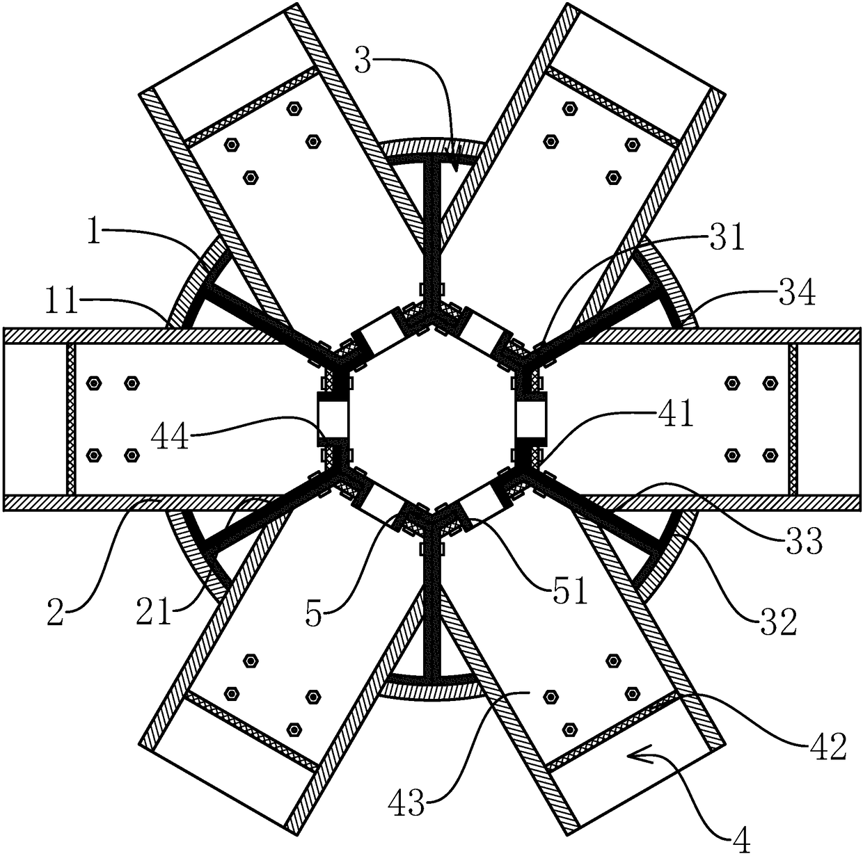
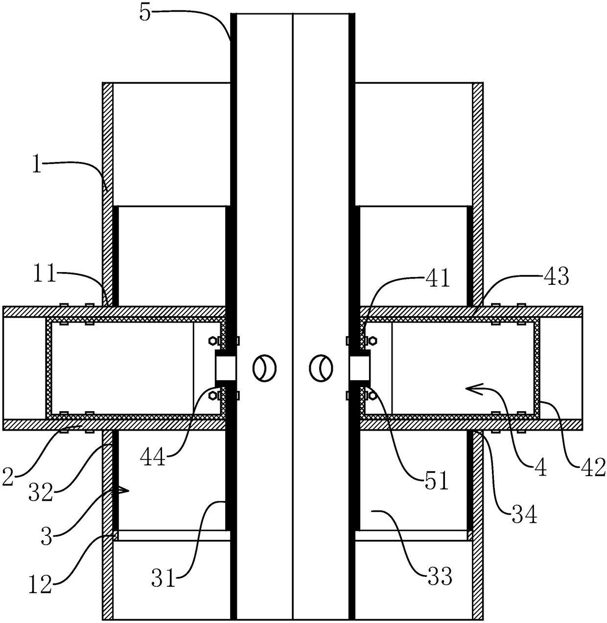
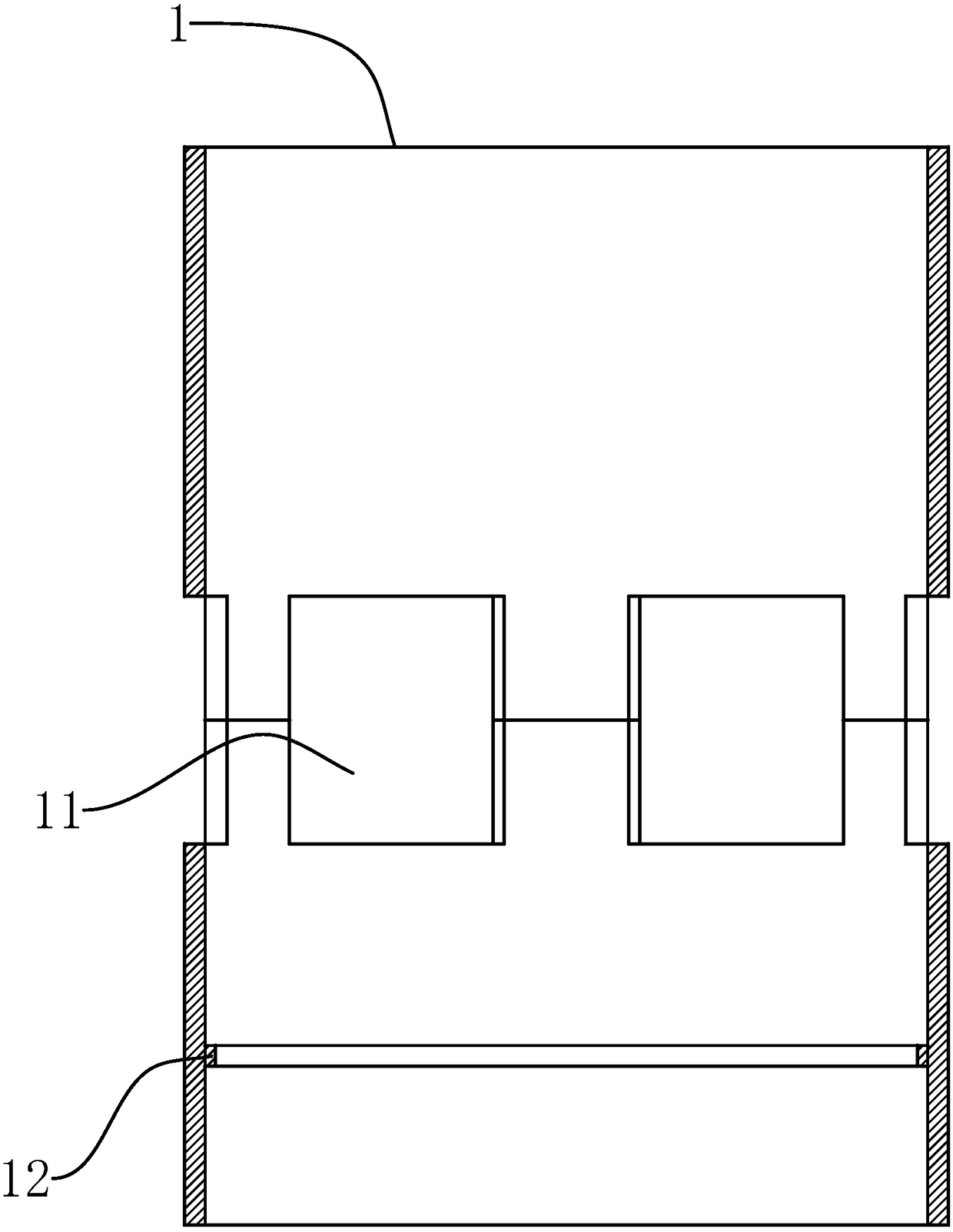
[0040] like Figure 1-3 As shown, a steel structure beam-column node of the present invention includes a vertically arranged circular tube cylinder 1 and a horizontally arranged square tube beam body 2, and also includes several nodes, and the nodes include a tubular central tube 5 with a regular polygonal cross section and A number of tubular post joints 3 with fan-shaped cross-sections. The post joints 3 include an inner post joint 31, an outer post joint 32 and two side post joints 33. The side post joints 33 of two adjacent post joints 3 The outer surfaces are sequentially bonded and connected, and a plurality of inner column connecting plates 31 are enclosed to form a regular polygonal tubular inner sleeve, and severa...


PUM


Abstract

The invention provides a steel structure beam column joint and a manufacture and installation method thereof, and belongs to the field of steel structures. The problem of lower strength of an existingbeam column joint is solved. The steel structure beam column joint includes a column body, a beam body and a joint, the joint includes a center pipe and a column connecting pipe, and the column connecting pipe includes inner column connecting plates, outer column connecting plates and two side column connecting plates; the inner column connecting plates are surrounded to form inner sleeves, the outer column connecting plates are surrounded to form outer connecting pipes, and the outer side of the center pipe is sleeved with the inner sleeves; the steel structure beam column joint further includes a beam connecting pipe embedded in the beam body end portion, the beam connecting pipe includes a front beam connecting plate, a rear beam connecting plate and a side beam connecting plate, and the left and right sides of the beam body end portion and the front beam connecting plate are aslant cut; the outer column connecting plate is provided with a beam connecting hole, the outer side surface of the front beam connecting plate and the inner side surface of the inner column connecting plate are fixed in a fit mode, and the beam connecting pipe and the two side column connecting plates are surrounded in the beam bodies to form a closed grouting area; and a grouting channel is formed in the center pipe, and communicated grouting holes are formed in the pipe wall of the center pipe, theinner column connecting pipe and the front beam connecting plate. The strength of the steel structure beam column joint is higher.

Description

technical field [0001] The invention belongs to the technical field of steel structures, and relates to a beam-column joint of a steel structure and a method for making and installing the same. Background technique [0002] In the steel structure buildings that are widely used at present, it is usually necessary to install the beam body on the side of the column body. The existing method generally directly connects the end of the beam body with the outer wall of the column through connecting steel plates, which not only needs to connect multiple steel plates, but also leads to low construction efficiency. At the same time, the connection between the steel plate and the beam body and the column body is under a large force, and the adjacent beam body is an independent structure, which cannot achieve a stable connection between the adjacent beam bodies, and the connection part is kept outside, which is easy to corrode and rust the connection parts, and then It affects the stabi...

Claims


Application Information

Patent Timeline
Patent Type & Authority Applications(China)
IPC IPC(8): E04B1/24E04B1/58
CPCE04B1/2403E04B2001/2406E04B2001/2427
Inventor 王斌辉
Owner 新昌县丽晶工业产品设计有限公司
Why Eureka
Try Eureka