

Wall-mounted air conditioner indoor unit
A technology for wall-mounted air conditioners and air conditioner indoor units, which is applied in air conditioning systems, heating methods, space heating and ventilation, etc., can solve the problems of small air guide range, limited swing angle of air guide plates, poor comfort experience, etc. Good air supply, improved comfort, and the effect of meeting diverse needs
- Summary
- Abstract
- Description
- Claims
- Application Information
AI Technical Summary
Problems solved by technology
Method used
Image

Examples
Embodiment Construction
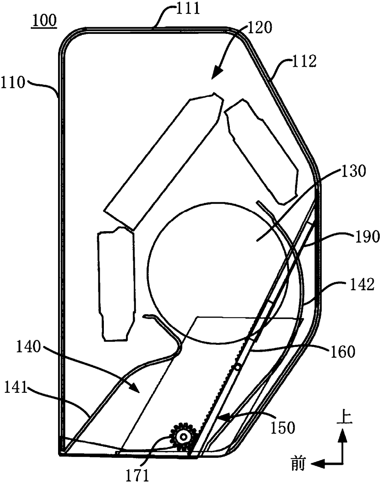
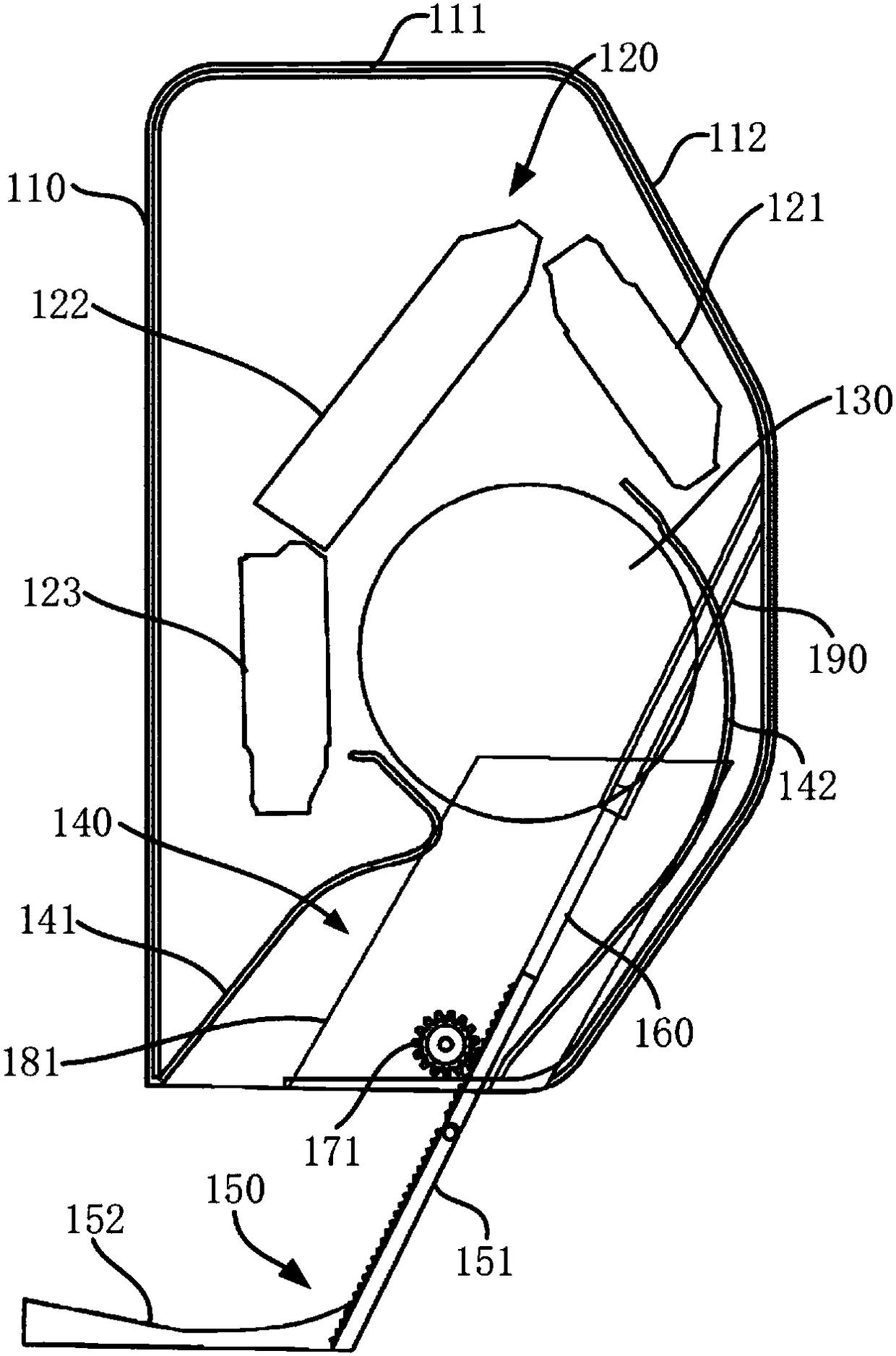
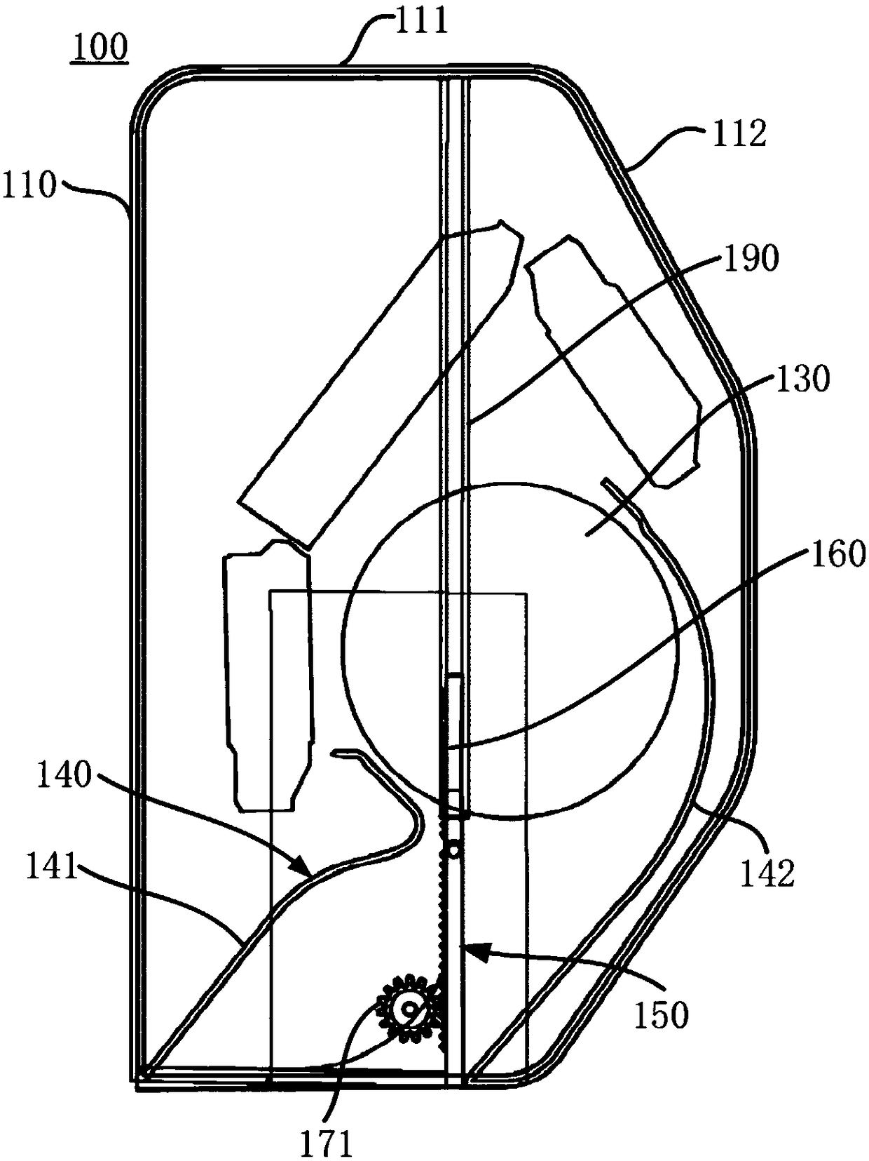
[0058] This embodiment firstly provides a wall-mounted air conditioner indoor unit 100, figure 1 It is a schematic structural diagram of the wall-mounted air conditioner indoor unit 100 according to the first embodiment of the present invention, wherein the wind deflector 150 is in the first position.
[0059] see figure 1 In general, the wall-mounted air conditioner indoor unit 100 may generally include a housing 110 , an indoor unit heat exchanger 120 and an indoor unit fan 130 disposed in the housing 110 . The top of the casing 110 is formed with a top air inlet 111, and the lower part of the casing 110 is formed with an air outlet extending in the lateral direction of the indoor unit 100. The inside of the casing 110 is provided with an air outlet duct 140 communicating with the air outlet. The channel 140 is defined by an upper channel wall 141 and a lower channel wall 142 . The indoor unit heat exchanger 120 may be configured to exchange heat with air flowing therethro...
PUM
 Abstract
Description
Claims
Application Information