Eureka AIR delivers breakthrough ideas for toughest innovation challenges, trusted by R&D personnel around the world.

Intelligent control safety check equipment

A security inspection and intelligent control technology, applied in the field of security inspection, can solve the problems of wasting energy, unable to increase speed, stampede accidents, etc., to achieve the effect of improving image resolution, avoiding overlapping occlusion, and reducing labor intensity

Inactive Publication Date: 2018-06-19
NORTHEASTERN UNIV
View PDF5 Cites 4 Cited by
  • Summary
  • Abstract
  • Description
  • Claims
  • Application Information

AI Technical Summary

Problems solved by technology

[0004] At present, the bottom-illuminated security inspection equipment has the following technical problems: (1) The transmission motor adopts a fixed speed mode, no matter how many packages there are, it runs at a fixed speed. When there are few packages, the speed cannot be reduced, which wastes energy; Increasing the pass rate will easily cause crowding, especially in the busy subway or train station peak hours, which will easily induce stampede accidents; (2) The opening angle of the ray source is fixed, even if it is a small package, the ray source will All angles are open to radiate high-energy rays outward, which will bring unnecessary radiation effects to surrounding pedestrians, staff and the environment, such radiation will especially have adverse effects on pregnant women and children; (3) due to passengers on the conveyor belt Placement of parcels is arbitrary. For parcels that are misplaced, the image on the screen is off-center, and a large part of the screen is blank, causing waste. The image on the screen is incomplete and clear, which affects normal security inspections.

Method used


Image

  • Intelligent control safety check equipment
  • Intelligent control safety check equipment
  • Intelligent control safety check equipment

Examples


Embodiment Construction

[0029] The present invention will be described in detail below in conjunction with the accompanying drawings, but the protection scope of the present invention is not limited by the accompanying drawings.

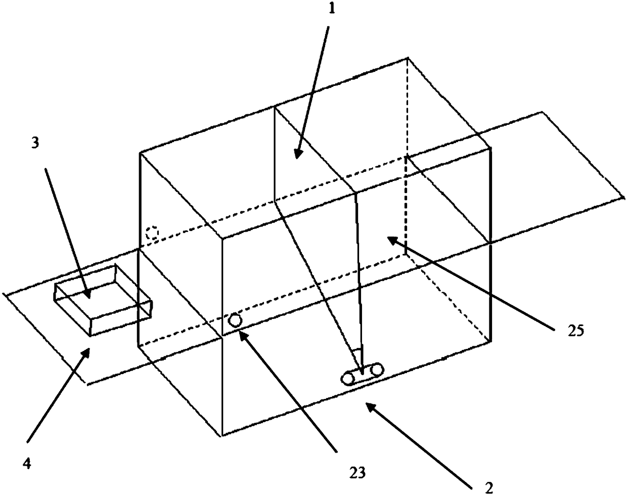
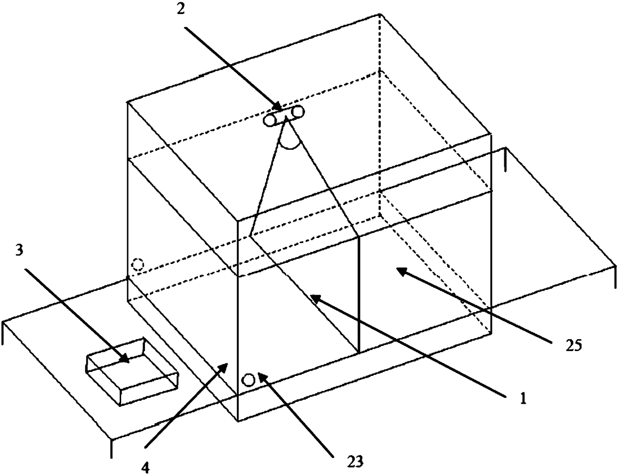
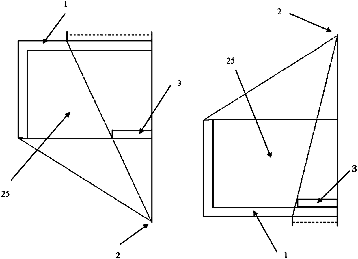
[0030] figure 1 It is a schematic diagram of the structure of the bottom-illuminated security inspection equipment, figure 2 It is a schematic diagram of the structure of the top-illuminated security inspection equipment, image 3 It is a structural comparison diagram of bottom-illuminated security inspection equipment and top-illuminated security inspection equipment. Such as image 3 As shown, the dotted line part shows the package of the same size. Under different illumination methods, the size of the image is larger, and the resolution of the larger image is higher, and the image is clearer. The safety inspection device of the present invention adopts the bottom-illuminated type, fully utilizes its geometric magnification feature, improves image resolution, and does...


PUM


Abstract

The invention belongs to the technical field of safety check, and specifically relates to intelligent control safety check equipment. The equipment is of a bottom irradiation type. A channel inlet isprovided with a lifting inclined surface, and an outlet is provided with a falling inclined surface. An auxiliary conveying belt is disposed in front of the lifting inclined surface, and an auxiliaryconveying belt support platform is provided with an infrared detector array. The auxiliary conveying belt is provided with a plurality of groups of wrapped detection holes. The infrared detector arraycan detect the size and position of a parcel in real time, and feeds back the size and position to a control program, and the control program controls the auxiliary conveying belt and a conveying belt according to the real-time state. An outlet of a ray source is provided with two lead blocks with the adjustable angles. The equipment gives consideration to the reduction of the labor intensity ofa visitor in carrying out the parcel, the avoiding of the stacking of parcels and the improvement of display resolution. The equipment adjusts the angles of the lead blocks according to the size and position of parcels, limits the irradiation range of rays, reduces the threads to the personnel and environment, adjusts the amplification scale of display and translation data according to the size and position of the parcel, and enables the display to be in a state facilitating the observation.

Description

technical field [0001] The invention belongs to the technical field of safety inspection, and in particular relates to an intelligent control safety inspection device. Background technique [0002] Radiation (including X-ray, γ-ray and others) security inspection equipment is an important equipment for customs, airports, railway stations, subways, express outlets and other transportation and public facilities to achieve security inspections. The first barrier of safety protection in the field of transportation and public safety provides scientific means for protecting personal and public property safety and combating smuggling activities. [0003] Existing security inspection equipment can be divided into bottom-illuminated, top-illuminated, and side-illuminated types according to the radiation mode. During the actual inspection, the package to be inspected usually enters the inspection channel horizontally, and the side-illuminated image overlaps seriously, so it is genera...

Claims


Application Information

Patent Timeline
IPC IPC(8): G01V5/00
CPCG01V5/00
Inventor 谭俊
Owner NORTHEASTERN UNIV
Why Eureka
Eureka Blog
Learn More