Head-up display system and control method thereof

A head-up display system and control method technology, applied in instruments, polarizing elements, optics, etc., can solve problems such as inability to display image information well, driver eye fatigue, etc.

Active Publication Date: 2018-06-19
BOE TECH GRP CO LTD
View PDF9 Cites 16 Cited by
  • Summary
  • Abstract
  • Description
  • Claims
  • Application Information

AI Technical Summary

Problems solved by technology

[0005] The present invention provides a head-up display system and its control method to solve the problem that the existing

Method used


Image

  • Head-up display system and control method thereof
  • Head-up display system and control method thereof
  • Head-up display system and control method thereof

Examples


Embodiment 1

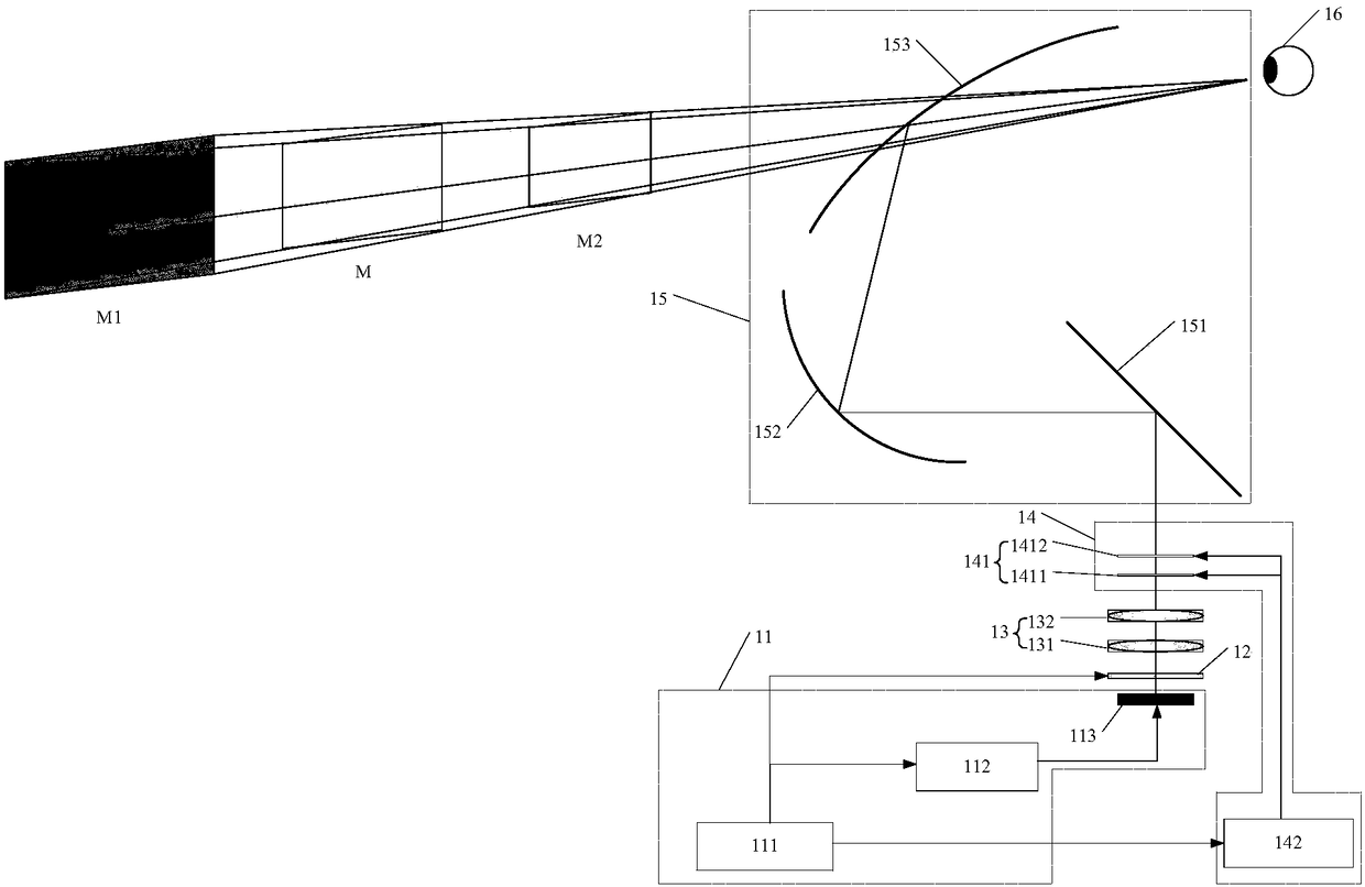
[0055] refer to figure 1 , showing a schematic diagram of a head-up display system according to an embodiment of the present invention.

[0056] An embodiment of the present invention provides a head-up display system, including: a display control component 11, a polarization conversion element 12, a birefringent lens component 13, a scattering component 14 and a reflection component 15; the display control component 11 is used for preset The first to-be-displayed image and the second to-be-displayed image are alternately output to the polarization conversion element 12 in sequence; the polarization conversion element 12 is used to convert the light of the first to-be-displayed image into S-polarized light, and to convert all the The light of the second to-be-displayed image is converted into P-polarized light, and is incident on the birefringent lens assembly 13; the birefringent lens assembly 13 is used to image the first to-be-displayed image converted into S-polarized ligh...

Embodiment 2

[0093] refer to Figure 5 , showing a flowchart of a control method for a head-up display system according to an embodiment of the present invention, which may specifically include the following steps:

[0094] Step 501 , in one display period, alternately output the first image to be displayed and the second image to be displayed to the polarization conversion element according to a preset timing sequence.

[0095] In the embodiment of the present invention, the head-up display system includes a light field display mode and a 2D display mode, and the light field display mode may be understood as a 3D display mode.

[0096] When the user selects the light field display mode, within one display period, the first image to be displayed and the second image to be displayed are alternately output to the polarization conversion element 12 according to a preset timing sequence.

[0097] Specifically, the image rendering unit 112 receives the first to-be-displayed image data and the ...


PUM


Abstract

The invention provides a head-up display system and a control method thereof, and relates to the field of display technologies. According to the invention, the conversion between light with differentpolarization states is performed through a polarization conversion element, images of a first projection plane and a second projection plane are simultaneously displayed by using a property of playingan imaging effect on light with an S polarization state and light with a P polarization state of a birefringent lens assembly and a scattering effect of a scattering assembly, and the light field display is realized through deep integration of the images of the two projection planes, thereby being capable of providing eye focusing adjustment within a certain depth range for a driver, displaying anatural 3D image, enabling the displayed image to be more authentic, and avoiding eye fatigue caused by long-term viewing of the driver.

Description

technical field [0001] The invention relates to the field of display technology, in particular to a head-up display system and a control method thereof. Background technique [0002] Head-up display (HUD), also known as head-up display, has gradually been widely used in the automotive field. The head-up display projects the important information and navigation information displayed by the instrument during the driving of the car to the front windshield, so that the driver can see the information in the instrument without lowering his head, which not only helps the novice who is inexperienced in speed judgment to control himself The speed of the vehicle can avoid the violation of regulations due to speeding in many speed-limited sections. More importantly, it can enable the driver to read instantaneously under the condition that the large field of view does not shift, and keep the best observation state with a clear head and avoid the driver bowing his head. Watch the instru...

Claims


Application Information

Patent Timeline
IPC IPC(8): G02B27/01G02B27/26G02B30/25
CPCG02B27/0101G02B2027/0196G02B30/25G02B2027/014G02F1/0134G02B5/30G02B2027/0185G02B2027/0145G02B27/286G02B1/08G02B5/3083G02B5/3016G02B27/0977G02B30/40
Inventor 洪涛
Owner BOE TECH GRP CO LTD
Why Eureka
Try Eureka