Bind type finger traction device

A traction device and binding technology, applied in medical science, fractures, passive exercise equipment, etc., can solve the problems of secondary injury of users, simple movement trajectory of traction fingers, complex control calculation, and complex mechanical structure, etc., to achieve sports Gentle trajectory, exquisite structure design, and the effect of improving the recovery effect

Inactive Publication Date: 2018-06-22
ANYANG INST OF TECH
View PDF5 Cites 2 Cited by
  • Summary
  • Abstract
  • Description
  • Claims
  • Application Information

AI Technical Summary

Problems solved by technology

[0002] my country is a country with a large population. Every year, there are a large number of people with finger dysfunction caused by hand trauma, brain trauma, and cerebrovascular diseases, and different degrees of finger motor dysfunction occur. Moreover, the hand is one of the important organs of the human body. Daily life and daily work need to be realized by hand. If the current finger traction training device is driven by a single motor, the movement trajectory of the traction finger is too simple, and the recovery of finger functions is not improved. If multi-motor traction is used, the control calculation, mechanical The structure is very complex, prone to failure, causing secondary damage to the user

Method used


Image

  • Bind type finger traction device
  • Bind type finger traction device
  • Bind type finger traction device

Examples


Embodiment Construction

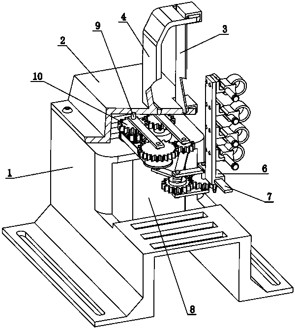
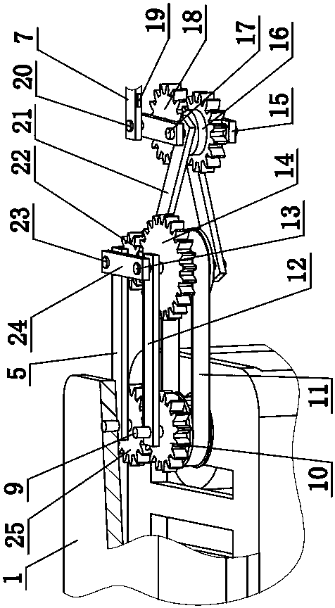
[0024] like Figure 1-6 , a binding finger traction device, including a support frame 1, a cover plate 2, a palm strap 3, a palm fixing frame 4, a first connecting rod 5, a finger connecting frame 6, a finger swing rod 7, a servo motor 8, a A column pin 9, the first double-coupling wheel 10, synchronous belt 11, the second connecting rod 12, the second column pin 13, the second double-coupling wheel 14, the third connecting rod 15, the third gear 16, the third column pin 17. Fourth gear 18, strain gauge 19, fourth pin 20, fourth connecting rod 21, fifth gear 22, fifth pin 23, fifth connecting rod 24, sixth gear 25, sixth connecting rod 26 , the seventh connecting rod 27, finger slide bar 28, bracket 29, finger slide block 30, finger cover 31, adjustment screw 32.

[0025] The cover plate 2 is fixed on the upper surface of the support frame 1, the palm fixing frame 4 is fixed on the cover plate 2, the upper end of the palm strap 3 is fixed on the palm fixing frame 4, and the l...


PUM


Abstract

The invention discloses a bind type finger traction device. The device includes a support frame and a servo motor; a first pin is fixed on the support frame, an output shaft of the servo motor fixes the rear ends of a sixth gear and a first connection rod, the first pin is rotatably connected with the rear ends of a first twin-wheel and a second connection rod, and a second pin is rotatably connected with the right end of a fifth connection rod, the front end of the second connection rod and the rear ends of a second twin-wheel and a sixth connection rod; a fifth pin is rotatably connected with the front end of the first pin, the left end of the fifth connection rod and the rear end of a fourth connection rod and fixedly connected with the rear ends of a fifth gear and the fourth connection rod; the sixth gear is meshed with a first gear of the first twin-wheel, the fifth gear is meshed with a second gear of the second twin-wheel, and a first belt pulley of the first twin-wheel and a second belt pulley of the second twin-wheel form a belt transmission; a third pin is rotatably connected with the right end of a seventh connection rod and the right end of a third connection rod, thefront end of a fourth connection rod and a third gear are fixed, a fourth pin is rotatably connected with the left end of the third connection rod, and the rear end of a finger swing rod and a fourthgear are fixed.

Description

technical field [0001] The invention relates to a finger pulling device, in particular to a binding finger pulling device. Background technique [0002] my country is a country with a large population. Every year, there are a large number of people with finger dysfunction caused by hand trauma, brain trauma, and cerebrovascular diseases, and different degrees of finger motor dysfunction occur. Moreover, the hand is one of the important organs of the human body. Daily life and daily work need to be realized by hand. If the current finger traction training device is driven by a single motor, the movement trajectory of the traction finger is too simple, and the recovery of finger functions is not improved. If multi-motor traction is used, the control calculation, mechanical The structures are all complicated, prone to breakdowns, and cause secondary injuries to users. [0003] This application adopts a single servo motor drive, through the two-stage linkage mechanism transmissio...

Claims


Application Information

Patent Timeline
Patent Type & Authority Applications(China)
IPC IPC(8): A61H1/02A61F5/042
CPCA61F5/0118A61F5/042A61H1/0218A61H1/0288A61H2201/14A61H2201/165A61H2201/50A61H2205/067
Inventor 翟亚芳卢春华杨欣鲁西坤李宏杰侯凡博
Owner ANYANG INST OF TECH
Why Eureka
Try Eureka