Dual-row-test-tube automatic adjusting centrifugal machine based on gear transmission

A technology of automatic adjustment and gear transmission, applied in centrifuges and other directions, can solve the problems of simple structure and low efficiency of centrifuges, and achieve the effect of high work efficiency

Active Publication Date: 2018-06-22
常州默里克仪器装备制造有限公司
View PDF4 Cites 4 Cited by
  • Summary
  • Abstract
  • Description
  • Claims
  • Application Information

AI Technical Summary

Problems solved by technology

[0002] At present, the existing centrifuges are simple in structure. In use, because the test tubes are fragile items, and because of the special shape of the test tubes, only one circle of test tubes is usually placed in the traditional centrifuge for centrifugation. In the same centrifuge Only one circ

Method used


Image

  • Dual-row-test-tube automatic adjusting centrifugal machine based on gear transmission
  • Dual-row-test-tube automatic adjusting centrifugal machine based on gear transmission
  • Dual-row-test-tube automatic adjusting centrifugal machine based on gear transmission

Examples


Embodiment Construction

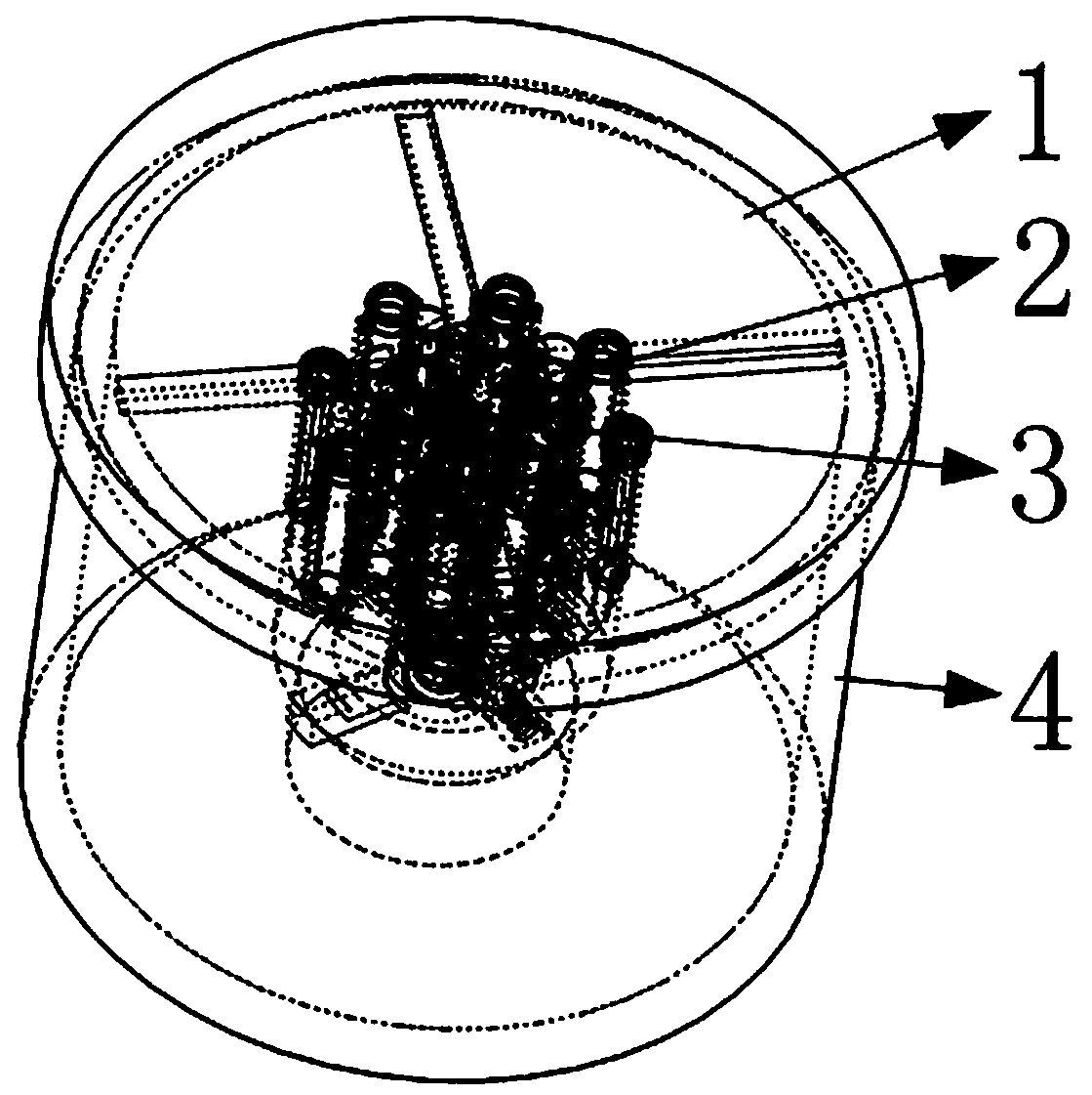
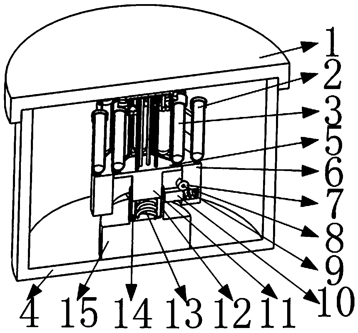
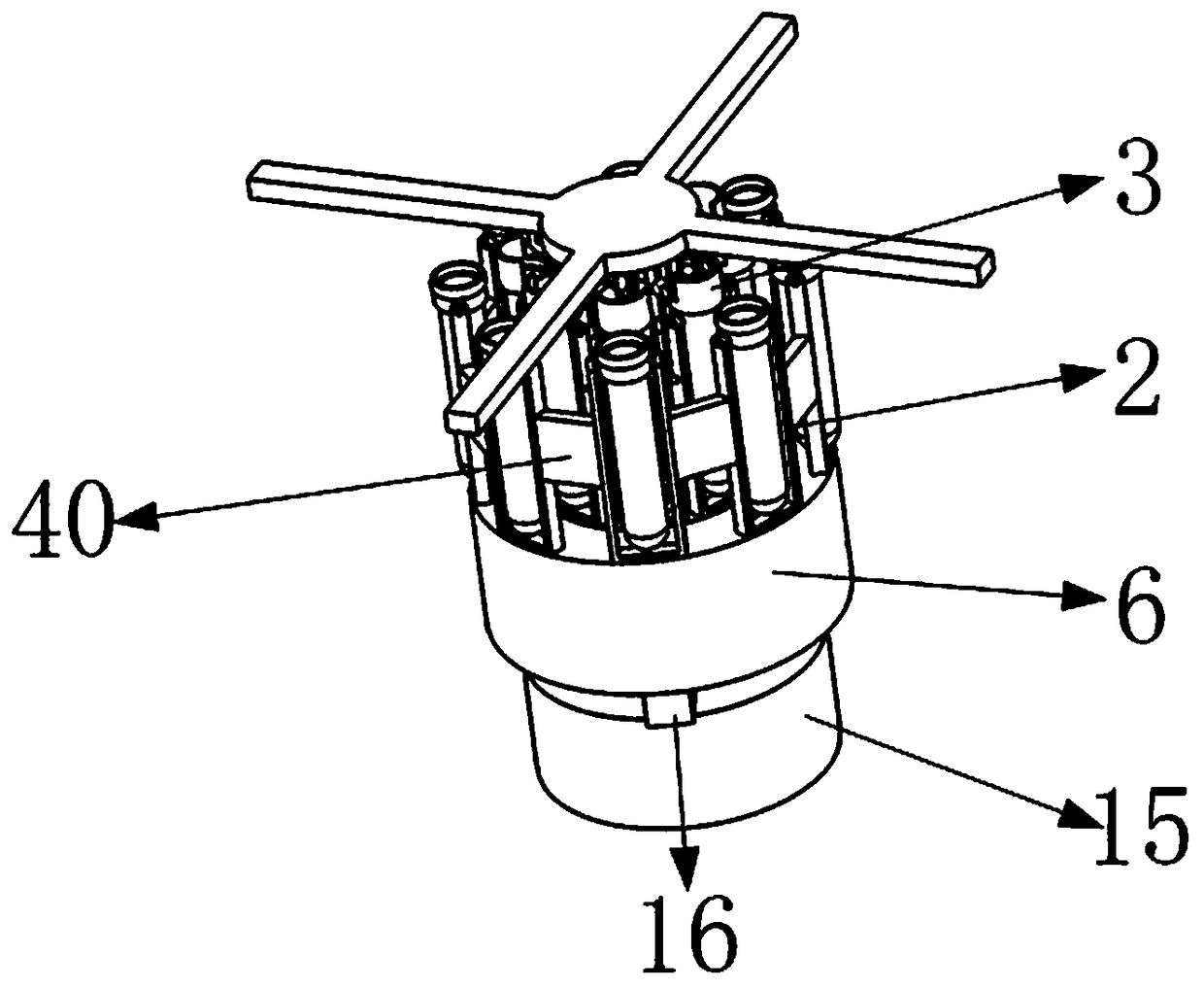
[0047] Such as figure 1 , 2 As shown, it includes a cover plate 1, a first centrifugal mechanism 2, a second centrifugal mechanism 3, a limit mechanism 42, a fixed shell 4, a second fixed ring 5, a first connecting block 40, a second connecting block 41, a driving ring 6. Drive gear 7, first fixed shaft 8, first spring 9, centrifugal block 10, drive shaft 11, motor shaft 12, second spring 13, guide groove 14, motor 15, L-shaped drive block 16, first circle Hole 17, shaft hole 18, semicircular groove 19, square groove 20, driving rack 21, second circular hole 22, guide bar 23, second fixed ring 5, as figure 2As shown, wherein the end face of the motor 15 is installed on the inner end face of the fixed shell 4; as Figure 9 As shown, the end face of the motor shaft 12 has a second circular hole 22; Figure 9 As shown, two guide grooves 14 are symmetrically opened on the inner circular surface of the second circular hole 22; Figure 8 As shown, one end of two L-shaped drivin...


PUM


Abstract

The invention belongs to the technical field of test tube centrifugal machines, and particularly relates to a dual-row-test-tube automatic adjusting centrifugal machine based on gear transmission. Thedual-row-test-tube automatic adjusting centrifugal machine based on gear transmission comprises a cover plate, a first centrifugal mechanism, a second centrifugal mechanism, a fixed shell, a second fixed ring, a first connecting block, a second connecting block, a drive ring, a drive gear and the like; the end face of an electric motor is arranged on the inner end face of the fixed shell, a second round hole is formed in the end face of a motor shaft, two guide grooves are symmetrically formed in the inner round face of the second round hole, and one ends of two L-shaped drive blocks are symmetrically arranged on the outer circular face of the motor shaft. The end face of the electric motor is arranged on the inner end face of the fixed shell, and the first centrifugal mechanism and the second centrifugal mechanism are conveniently driven to move; dual rows of test tubes are arranged in the centrifugal machine. Compared with a traditional centrifugal machine, the centrifugal machine is higher in work efficiency.

Description

technical field [0001] The invention belongs to the technical field of test tube centrifuges, in particular to a gear-driven double-row test tube automatic adjustment centrifuge. Background technique [0002] At present, the existing centrifuges are simple in structure. In use, because the test tubes are fragile items, and because of the special shape of the test tubes, only one circle of test tubes is usually placed in the traditional centrifuge for centrifugation. In the same centrifuge Only one circle of centrifuge test tubes can be placed under the device, so the efficiency of the centrifuge at this time is relatively low. In order to improve the use efficiency of the centrifuge, it is very useful to design a double-row test tube automatic adjustment centrifuge based on gear transmission. necessary. [0003] The present invention designs a double-row test tube automatic adjustment centrifuge based on gear transmission to solve the above problems. Contents of the inven...

Claims


Application Information

Patent Timeline
IPC IPC(8): B04B5/04B04B9/08B04B7/00
CPCB04B5/0414B04B9/02B04B9/08
Inventor 王杰
Owner 常州默里克仪器装备制造有限公司
Why Eureka
Try Eureka