Automatic collecting device for bearing sleeve

A technology for automatic collection and bearing sleeves, applied in metal processing and other directions, can solve the problems of inability to realize automatic and rapid collection of bearing sleeves, slow sorting speed, and high labor costs, and achieve the effects of saving labor and material resources, accurate rotation angle, and simple transmission structure.

Pending Publication Date: 2018-06-22
刘国冲
View PDF0 Cites 5 Cited by
  • Summary
  • Abstract
  • Description
  • Claims
  • Application Information

AI Technical Summary

Problems solved by technology

[0002] The bearing ring is a standard part of the bearing. In the existing processing technology, the bearing ring is pressed and cut by a bar or a plate. After forming, the bearing ring is in the shape of a ring-shaped sheet. The collection is often carried out manually, the sorting speed is slow, and the labor cost is high. In the existing work, the bearing sleeves need to be sorted and connected in series. However, there is no equipment in the prior art to match the above actions, and the bearing sleeves cannot be realized. automatic quick collection

Method used


Image

  • Automatic collecting device for bearing sleeve
  • Automatic collecting device for bearing sleeve
  • Automatic collecting device for bearing sleeve

Examples


Embodiment approach

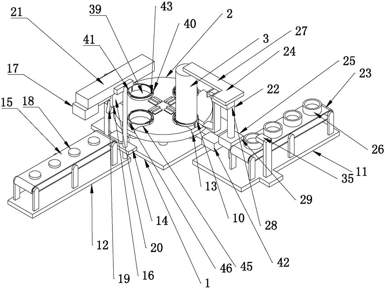
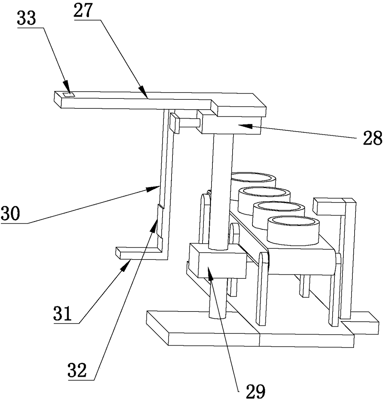
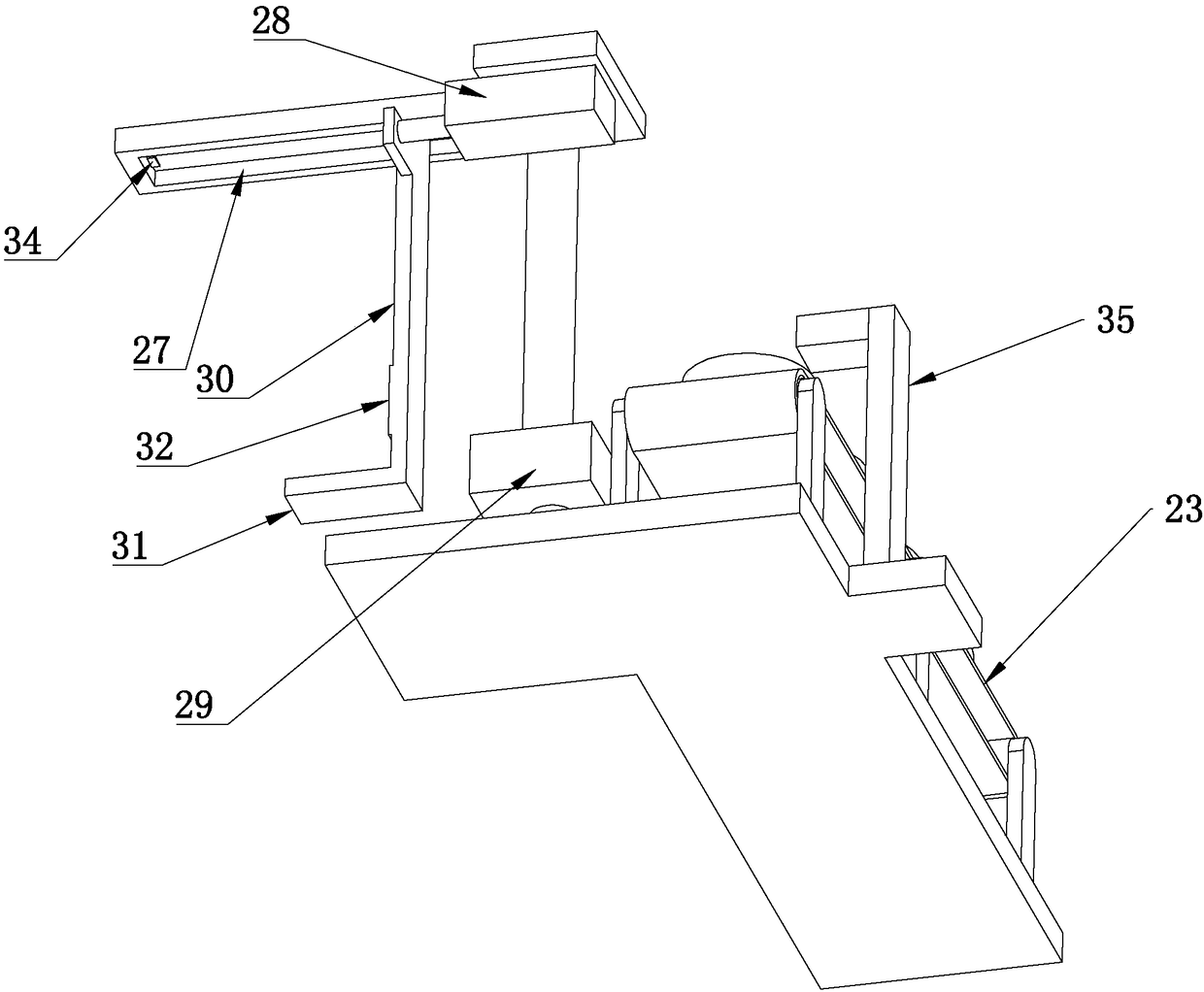
[0037] As an improved specific embodiment, the unloading device 11 includes a second installation frame 22, a second conveyor belt 23, a transfer frame 24, and a driving assembly 25 that drives the transfer frame 24 to move between the mounting base 10 and the second conveyor belt 23 , the second conveyor belt 23 is provided with several second receiving seats 26 arranged at equal intervals, and the second conveyor belt 23 is used to transfer the fully loaded collection cylinder 3 to the next station,

[0038] The second installation frame 22 is provided with a sliding seat 27, the transfer frame 24 is slidably connected with the sliding seat 27, the sliding seat 27 is arranged in parallel with the pushing groove 13, and the sliding seat 27 is connected with the second The mounting frame 22 is rotationally connected, and the driving assembly 25 includes a second driving device 28 and a third driving device 29, the second driving device 28 drives the transfer frame 24 to slide a...


PUM


Abstract

The invention discloses an automatic collecting device for a bearing sleeve. The automatic collecting device comprises a base, a conveying table, a collecting drum and a sensing and driving assembly.The conveying table and the base are connected rotationally. The conveying table is provided with a mounting seat. The collecting drum is detachably connected with the mounting seat. The sensing and driving assembly comprises a fourth driving device for driving the conveying table to rotate and a sensing device for judging whether the collecting drum is loaded fully or not. An unloading device anda loading device are arranged around the conveying table. The unloading device is used for conducting material unloading on the fully-loaded collecting drum. The loading device is used for mounting the hollow collecting drum on the mounting seat. By arranging a circular pin column and a transmission cam for driving the circular pin column on the back surface of the conveying table, when a drivingmotor drives the transmission cam to rotate, the transmission cam pushes the circular pin column to move, the transmission structure of the automatic collecting device is simple, the rotating angle of the conveying table is accurate, the whole collecting device can achieve high automation of collecting and packing movements of the bearing sleeve, and manpower and material resources are saved.

Description

technical field [0001] The invention relates to the field of bearing production equipment, in particular to an automatic collection device for bearing sleeves. Background technique [0002] The bearing ring is a standard part of the bearing. In the existing processing technology, the bearing ring is pressed and cut by a bar or a plate. After forming, the bearing ring is in the shape of a ring-shaped sheet. The collection is often carried out manually, the sorting speed is slow, and the labor cost is high. In the existing work, the bearing sleeves need to be sorted and connected in series. However, there is no equipment in the prior art to match the above actions, and the bearing sleeves cannot be realized. Automatic and fast collection. Contents of the invention [0003] Aiming at the deficiencies in the prior art, the object of the present invention is to provide an automatic collection device for bearing sleeves, so as to save manpower and speed up the production rate. ...

Claims


Application Information

Patent Timeline
Patent Type & Authority Applications(China)
IPC IPC(8): B23Q7/16
CPCB23Q7/16
Inventor 刘国冲刘安雷
Owner 刘国冲
Why Eureka
Try Eureka