Catheter tip-end rotation angle measurement apparatus, catheter tip-end rotation angle measurement method, and catheter tip-end rotation angle measurement program

a technology of rotation angle measurement and measurement method, which is applied in the direction of instruments, catheters, applications, etc., can solve the problem that the rotation angle at the tip end of the catheter cannot be accurately grasped, and achieve the effect of accurate measuremen

Active Publication Date: 2014-07-03
PANASONIC CORP
View PDF2 Cites 7 Cited by
  • Summary
  • Abstract
  • Description
  • Claims
  • Application Information

AI Technical Summary

Benefits of technology

[0019]According to the aspect of the present invention, the rotati...

Problems solved by technology

However, with the method of Patent Literature 1, in the case where the rotation angle at the hand of the surgeon and the rotatio...

Method used


Image

  • Catheter tip-end rotation angle measurement apparatus, catheter tip-end rotation angle measurement method, and catheter tip-end rotation angle measurement program
  • Catheter tip-end rotation angle measurement apparatus, catheter tip-end rotation angle measurement method, and catheter tip-end rotation angle measurement program
  • Catheter tip-end rotation angle measurement apparatus, catheter tip-end rotation angle measurement method, and catheter tip-end rotation angle measurement program

Examples


first embodiment

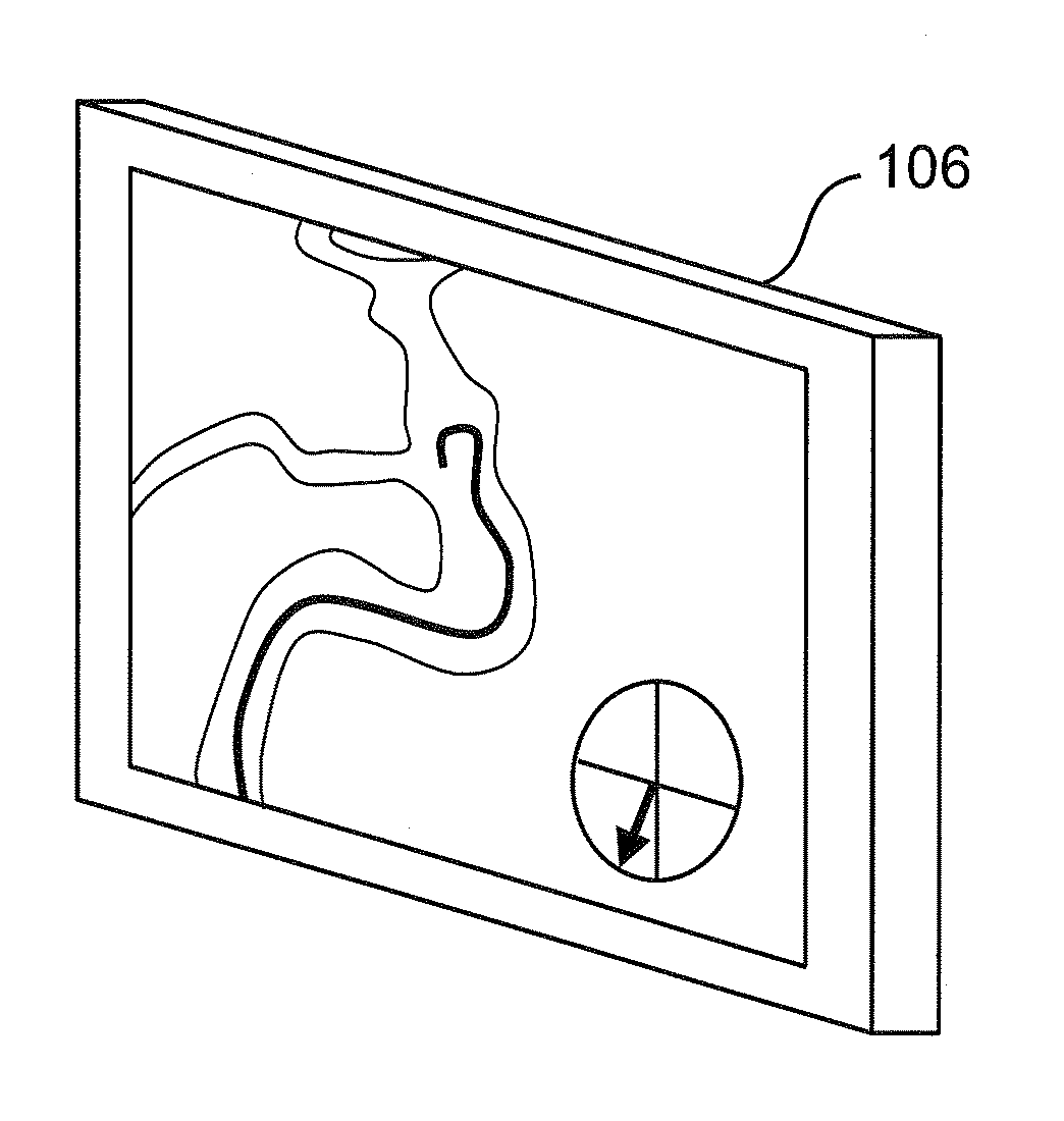
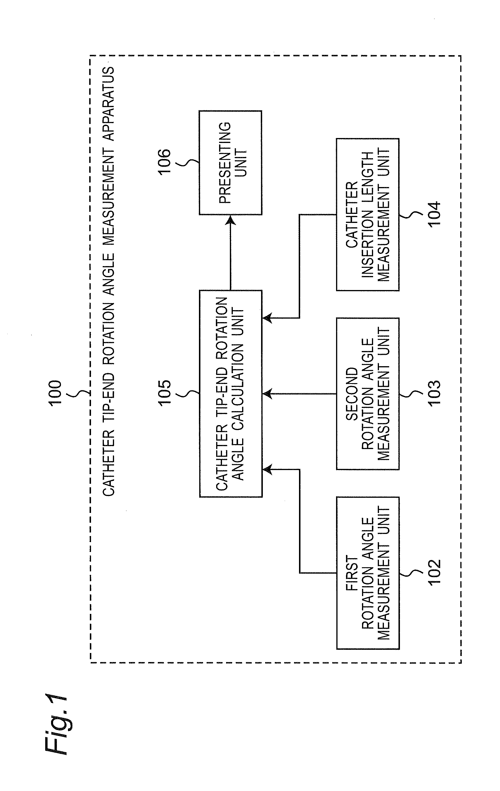
[0102]FIG. 1 shows a functional configuration of a catheter tip-end rotation angle measurement apparatus 100 according to a first embodiment.

[0103]As shown in FIG. 1, the catheter tip-end rotation angle measurement apparatus 100 includes a first rotation angle measurement unit 102, a second rotation angle measurement unit 103, a catheter insertion length measurement unit 104, and a catheter tip-end rotation angle calculation unit 105. Also, a movement restriction unit 101, not shown, is included. In the following, each structural element of the catheter tip-end rotation angle measurement apparatus 100 will be described.

[0104]

101>

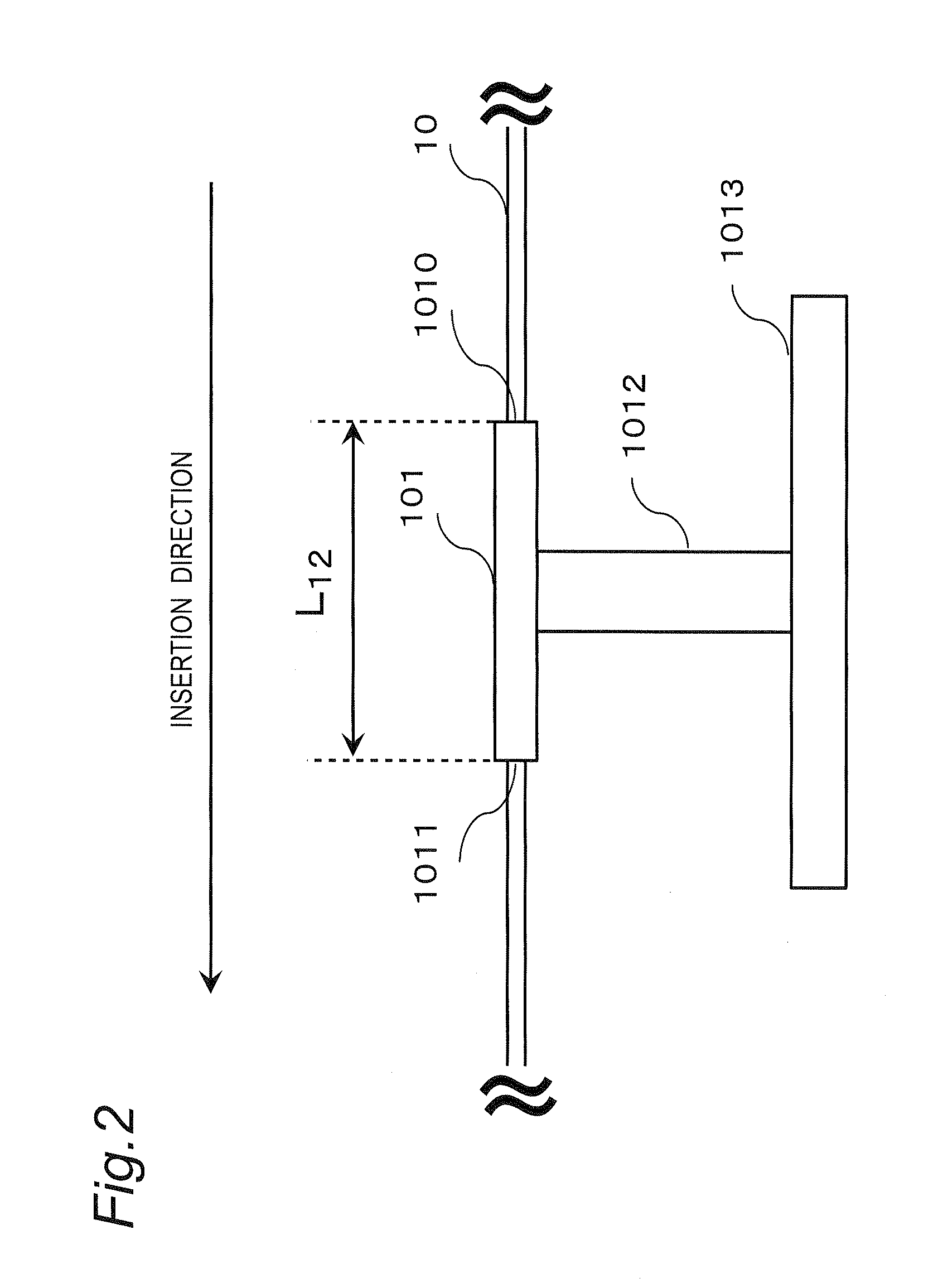
[0105]The movement restriction unit 101 has a tube shape which is penetrated from a first hole 1010 to a second hole 1011, and the movement of a catheter 10 is restricted to the insertion direction by causing the catheter 10 to pass through from the first hole 1010 to the second hole 1011.

[0106]FIG. 2 shows a schematic example of the movement restriction uni...

second embodiment

[0195]A catheter tip-end rotation angle measurement apparatus 200 according to a second embodiment is different from the catheter tip-end rotation angle measurement apparatus 100 of the first embodiment in that the catheter tip-end rotation angle measurement apparatus 200 detects the motion of the tip end portion 15 of the catheter 10, and in the case where movement is detected, the rotation angle θ of the tip end of the catheter 10 is calculated, and in the case where movement is not detected, the rotation angle θ of the tip end of the catheter 10 is not calculated. In the following, differences to the first embodiment will be mainly described.

[0196]FIG. 14 shows a functional configuration of the catheter tip-end rotation angle measurement apparatus 200 according to the second embodiment. Additionally, in FIG. 14, structural elements the same as those in FIG. 1 are denoted by the same reference numerals, and description thereof will be omitted as appropriately.

[0197]As shown in FIG...

third embodiment

[0232]A catheter tip-end rotation angle measurement apparatus 300 according to a third embodiment is different from the catheter tip-end rotation angle measurement apparatus 100 according to the first embodiment in that the catheter tip-end rotation angle measurement apparatus 300 is capable of accurately measuring the rotation angle of the tip end of a catheter 10 even in a case where a part of the catheter 10 is twisted. In the following, differences to the first embodiment will be mainly described.

[0233]FIG. 20 shows a functional configuration of the catheter tip-end rotation angle measurement apparatus 300 according to the third embodiment. Additionally, in FIG. 20, structural elements the same as those in FIG. 1 are denoted by the same reference numerals, and description thereof will be omitted as appropriately.

[0234]As shown in FIG. 20, the catheter tip-end rotation angle measurement apparatus 300 includes the first rotation angle measurement unit 102, the second rotation angl...


PUM


Abstract

A catheter tip-end rotation angle measurement apparatus includes a motion restriction unit, of a tube shape penetrated from a first hole to a second hole of a catheter on tip end and opposite sides, that restricts the catheter motion to an insertion direction by causing the catheter to pass through from the first to second holes, first and second rotation angle measurement units that measure first and second rotation angles that are rotation angles of the catheter at the first and second holes, a catheter insertion length measurement unit that measures a catheter insertion length, and a catheter tip-end rotation angle calculation unit that calculates the rotation angle of the catheter tip end by using an angle difference between the first and second rotation angles, the catheter insertion length, and a distance between the first and second holes.

Description

CROSS-REFERENCE TO RELATED APPLICATIONS[0001]This is a continuation application of International Application No. PCT / JP2013 / 003485, with an international filing date of Jun. 3, 2013, which claims priority of Japanese Patent Application No.: 2012-129552 filed on Jun. 7, 2012, the content of which is incorporated herein by reference.TECHNICAL FIELD[0002]The technical field relates to a catheter tip-end rotation angle measurement apparatus, a catheter tip-end rotation angle measurement method, and a catheter tip-end rotation angle measurement program for measuring the rotation angle of a tip end of a catheter.BACKGROUND ART[0003]In recent years, diagnosis or treatment of a lesion or a stenosis is performed by inserting a catheter into a blood vessel or the like of a patient (for example, PCI (Percutaneous Coronary Intervention) or TAE (Transcatheter Arterial Embolisation)).[0004]During the diagnosis or treatment, a surgeon manipulates the catheter while monitoring an X-ray fluoroscopic...

Claims


Application Information

Patent Timeline
IPC IPC(8): A61B6/12
CPCA61B6/12A61B6/461A61M25/0105G09B23/285
Inventor NAKADA, TORUKOZUKA, KAZUKISATO, TAICHI
Owner PANASONIC CORP
Why Eureka
Try Eureka