Laser welding device

A laser welding and fixing device technology, applied in laser welding equipment, auxiliary equipment, welding equipment, etc., can solve the problems of difficult control of rotation angle and lifting height, uneven distribution of solder joints, etc., and achieve high degree of automation and smooth distribution of solder joints Uniformity, work efficiency improvement effect

Active Publication Date: 2013-06-26
HANS LASER TECH IND GRP CO LTD
View PDF9 Cites 9 Cited by
  • Summary
  • Abstract
  • Description
  • Claims
  • Application Information

AI Technical Summary

Problems solved by technology

Since this type of device is manual, the rotation angle and lifting height are not easy to control, resulting in uneven distribution of solder points during multi-point welding

Method used


Image

  • Laser welding device
  • Laser welding device
  • Laser welding device

Examples


Embodiment Construction

[0040] In order to facilitate the understanding of the present invention, the present invention will be described more fully below with reference to the associated drawings. Preferred embodiments of the invention are shown in the accompanying drawings. However, the present invention can be embodied in many different forms and is not limited to the embodiments described herein. On the contrary, these embodiments are provided to make the understanding of the disclosure of the present invention more thorough and comprehensive.

[0041] It should be noted that when an element is referred to as being “fixed” to another element, it can be directly on the other element or there can also be an intervening element. When an element is referred to as being "connected to" another element, it can be directly connected to the other element or intervening elements may also be present.

[0042] Unless otherwise defined, all technical and scientific terms used herein have the same meaning as...


PUM


Abstract

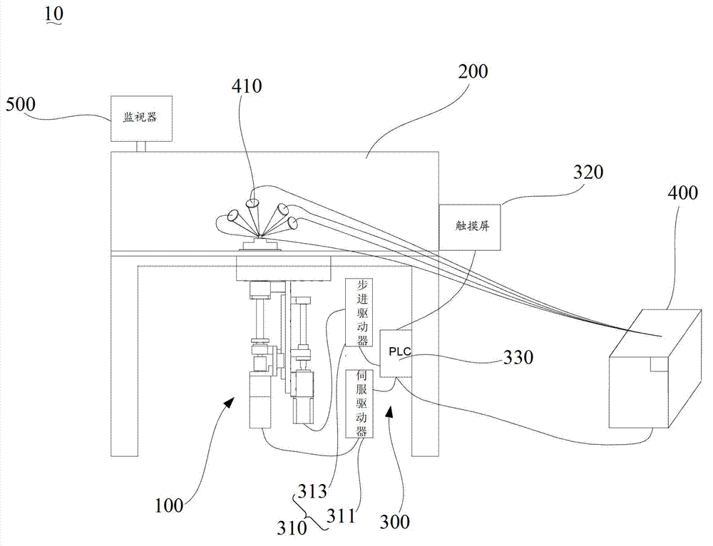
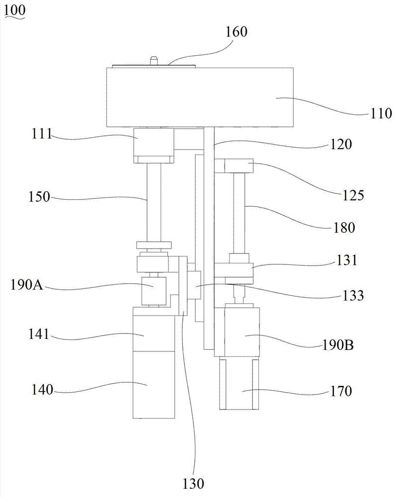
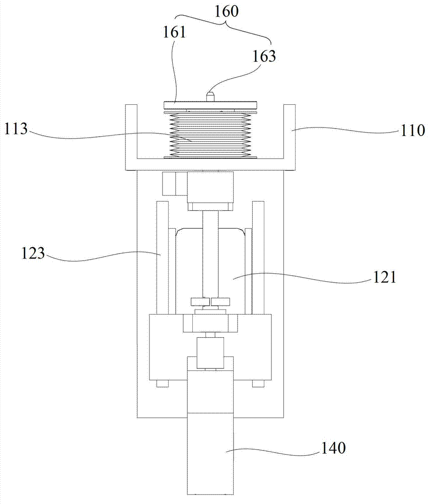
The invention relates to a laser welding device comprising a worktable, a weld fixing device and a control device, wherein the weld fixing device comprises a fixing plate, a vertical plate, a connecting plate, a first motor, a rotating shaft, a workpiece fixing structure, a second motor and a lead screw; the rotation motion of the workpiece fixing structure is controlled through the first motor; and the rotating speed of the workpiece fixing structure is determined by the rotating speed of an output shaft of the first motor. According to the invention, the rotating speed of the first motor can be set to a preset value, so that the accurate rotation angle of the workpiece fixing structure is guaranteed; in addition, the lifting motion of the workpiece fixing structure is realized through driving the lead screw by using the second motor and cooperating with a lead screw nut; the circular motion of the second motor can be transformed into accurate linear motion through the cooperation of the lead screw and the lead screw nut, so that the control of the lifting height can be realized through controlling the rotating speed of the second motor; and therefore, the weld fixing device is capable of effectively controlling the rotation angle and the lifting height of the workpiece fixing structure and welding spots are uniformly distributed during multiple-spot welding.

Description

technical field [0001] The invention relates to welding technology, in particular to a laser welding device. Background technique [0002] When soldering and packaging optoelectronic devices, it is often necessary to solder multiple solder joints. The plurality of solder joints are located in different focal planes, and each focal plane has multiple solder joints. During the welding process, in order to ensure the welding accuracy, the laser used for welding is generally fixed, and the workpiece to be welded is moved. The welding of multiple solder joints in the same focal plane is generally realized by rotating the workpiece; while the welding of solder joints with different focal planes is realized by lifting the workpiece. [0003] In the traditional welding process, a manual welding device is generally used to fix the workpiece to be welded and drive the workpiece to move. The manual welding device uses the hand wheel to control the lifting of the worm structure, and ...

Claims


Application Information

Patent Timeline
Patent Type & Authority Applications(China)
IPC IPC(8): B23K26/22B23K37/047
Inventor 张圣锋彭伟东刘永福赵永金高云峰
Owner HANS LASER TECH IND GRP CO LTD
Why Eureka
Try Eureka