Eureka AIR delivers breakthrough ideas for toughest innovation challenges, trusted by R&D personnel around the world.

Building brick shape-fixing cutting equipment

A technology for construction and bricks, which is applied to stone processing equipment, stone processing tools, work accessories, etc., can solve the problems of inability to cut obliquely, reduce the life of cutting saw blades, and waste, so as to facilitate stereotyped cutting, The effect of reducing work errors and wide application range

Inactive Publication Date: 2018-06-22
魏敏生
View PDF8 Cites 4 Cited by
  • Summary
  • Abstract
  • Description
  • Claims
  • Application Information

AI Technical Summary

Problems solved by technology

[0003] The size of ordinary standard red bricks is 240*115*53, but in some specific cases, the size of red bricks is not fixed. Generally, red bricks are used in construction to build load-bearing and non-load-bearing walls. In some wall corners Or in special cases, in order to ensure the orderliness of the wall, it is necessary to cut off the standard red bricks for use. Workers generally use a small hammer to break them according to experience. Manual operations are prone to errors and cause waste, and the shapes of the cut bricks are not uniform, let alone For oblique cutting, design an automatic brick cutting device to ensure that the device can cut according to a specific size. In addition, it is necessary to prevent the dust generated during the cutting process from spreading, and during continuous cutting, the temperature of the cutting saw blade If the temperature rises sharply, if the temperature is not lowered in time, the life of the cutting saw blade will be sharply reduced, so it is necessary to set this device

Method used


Image

  • Building brick shape-fixing cutting equipment
  • Building brick shape-fixing cutting equipment

Examples


Embodiment Construction

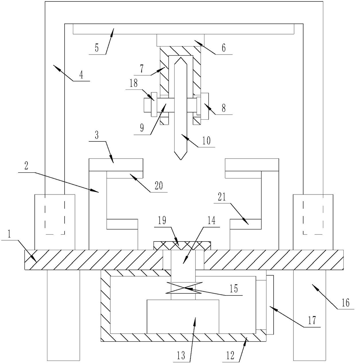
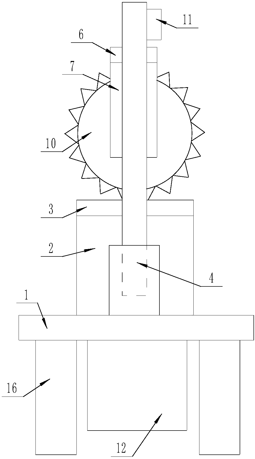
[0014] The present invention is specifically described below in conjunction with accompanying drawing, as Figure 1-2 As shown, a kind of stereotyped brick cutting equipment for construction, including a mounting base 1, a pair of L-shaped positioning plates 2 are fixedly connected to both ends of the upper surface of the mounting base 1, and the upper surface of each of the L-shaped positioning plates 2 is fixed A fixed pressure plate 3 is connected, the upper surface of the mounting seat 1 is fixedly connected with an electric control telescopic gantry frame 4, and the lower surface of the crossbeam of the electric control telescopic gantry frame 4 is fixedly connected with a horizontal slide rail 5, and the horizontal slide rail 5 is fixedly connected with the horizontal slide rail 5. The lower surface of the rail 5 is provided with an electronically controlled mobile slider 6, and the lower surface of the electrically controlled mobile slider 6 is fixedly connected with a d...


PUM


Abstract

The invention discloses building brick shape-fixing cutting equipment. The building brick shape-fixing cutting equipment comprises an installation seat; the two ends of the upper surface of the installation seat are fixedly connected with a pair of L-shaped positioning plates; the upper surface of each L-shaped positioning plate is fixedly connected with a fixed pressing plate; the upper surface of the installation seat is fixedly connected with an electrically-controlled telescopic door-shaped frame; the lower surface of a transverse beam of the electrically-controlled telescopic door-shapedframe is fixedly connected with a transverse slide rail; an electrically-controlled movable slide block is arranged on the lower surface of the transverse slide rail, and the lower surface of the electrically-controlled movable slide block is fixedly connected with a door-shaped fixed frame; installation holes are machined in supporting legs of the door-shaped fixed frame, and a cutting motor of which the driving end is in the horizontal direction is embedded in one of the installation holes; the rotary end of the cutting motor is fixedly connected with a connection shaft stretching out through the other installation hole, and the connection shaft is sleeved with a cutting saw web. The building brick shape-fixing cutting equipment has the beneficial effects of being simple in structure andhigh in practicality.

Description

technical field [0001] The invention relates to the field of building construction tools, in particular to equipment for shaping and cutting bricks for building. Background technique [0002] Red brick is a sintered building made of clay, shale, coal gangue, etc., which are crushed, mixed and kneaded, pressed manually or mechanically, and fired with an oxidizing flame at a temperature of about 900 degrees Celsius after drying. bricks. [0003] The size of ordinary standard red bricks is 240*115*53, but in some specific cases, the size of red bricks is not fixed. Generally, red bricks are used in construction to build load-bearing and non-load-bearing walls. In some wall corners Or in special cases, in order to ensure the orderliness of the wall, it is necessary to cut off the standard red bricks for use. Workers generally use a small hammer to break them according to experience. Manual operations are prone to errors and cause waste, and the shapes of the cut bricks are not ...

Claims


Application Information

Patent Timeline
Patent Type & Authority Applications(China)
IPC IPC(8): B28D1/04B28D1/10B28D7/02B28D7/04
CPCB28D1/043B28D1/044B28D1/10B28D7/02B28D7/04
Inventor 魏敏生
Owner 魏敏生
Why Eureka
Eureka Blog
Learn More