Mechanism for detecting flatness of injection molding part

A technology for detecting mechanism and flatness, which is applied in the field of flatness detection mechanism for injection molded parts, and can solve problems such as inability to distinguish between sags and bulges

Inactive Publication Date: 2018-06-22
重庆雷钜电子科技有限公司
View PDF6 Cites 2 Cited by
  • Summary
  • Abstract
  • Description
  • Claims
  • Application Information

AI Technical Summary

Problems solved by technology

[0004] The disadvantage of the above method is that it is impossible to distinguish the two types of unevenness, the depression and the protrusion, and the degree of the depression and the protrusion cannot be distinguished

Method used


Image

  • Mechanism for detecting flatness of injection molding part

Examples


Embodiment Construction

[0024] The following is further described in detail through specific implementation methods:

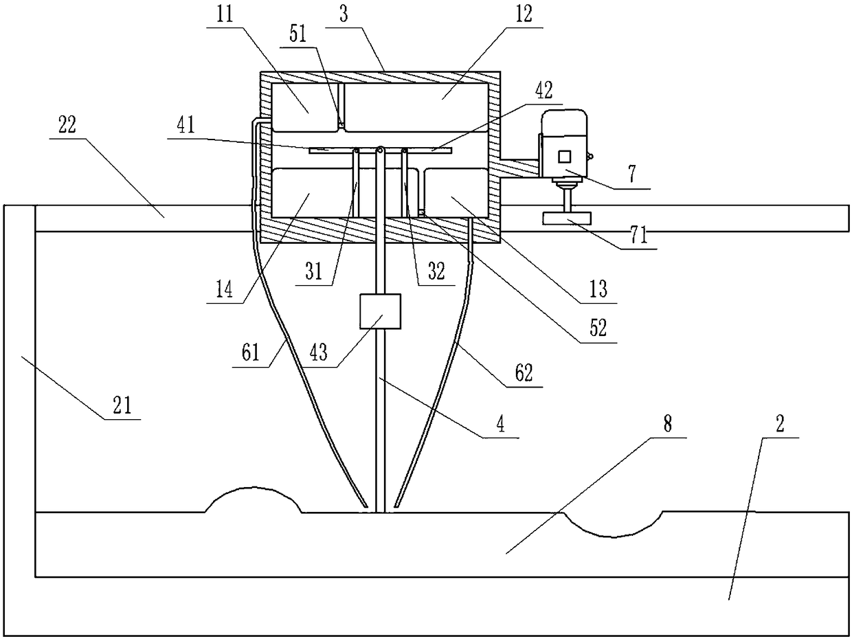
[0025] The reference signs in the accompanying drawings of the description include: the first elastic bag 11, the second elastic bag 12, the third elastic bag 13, the fourth elastic bag 14, the processing table 2, the bracket 21, the guide rail 22, the sliding seat 3, the first Connecting rod 31, second connecting rod 32, detection rod 4, first fork 41, second fork 42, first hose 51, second hose 52, first nozzle 61, second nozzle 62, Motor 7, gear 71, counterweight 43, injection molding part 8.

[0026] The embodiment is basically as attached figure 1 As shown: the flatness detection mechanism of injection molded parts includes a processing table 2, a bracket 21 and a detection mechanism. A guide rail 22 is arranged on the bracket 21, and the guide rail 22 is arranged horizontally and is located above the processing table 2; the detection mechanism includes a sliding seat 3 and the...


PUM


Abstract

The invention relates to the technical field of detection equipment, in particular to a mechanism for detecting the flatness of an injection molding part. The mechanism comprises a machining table, asupport and a detection mechanism, wherein a guide rail is arranged on the support; the detection mechanism comprises a sliding seat and a detection rod, the sliding seat is slidably connected to theguide rail, a cavity is formed in the sliding seat, and a vertical sliding hole is formed in the bottom of the sliding seat; the middle of the detection rod is slidably connected in the sliding hole of the sliding seat, a first connecting rod, a second connecting rod, a first swinging rod and a second swinging rod are arranged in the cavity of the sliding seat, the first connecting rod and the second connecting rod are both fixed on the inner wall of the sliding seat, the first connecting rod and the second connecting rod are located on the two sides of the detection rod respectively, the middle of the first swinging rod is hinged to the first connecting rod, the middle of the second swinging rod is hinged to the second connecting rod, the end portion of the first swinging rod is hinged tothe upper portion of the detection rod, and the end portion of the second swinging rod is hinged to the upper portion of the detection rod. The invention aims to provide the mechanism for detecting the flatness of the injection molding part, and the mechanism can be used for distinguishing the degree of the pits and the degree of the protrusions and marking the pits and the protrusions.

Description

technical field [0001] This patent relates to the technical field of testing equipment, in particular to a flatness testing mechanism for injection molded parts. Background technique [0002] In the production process of injection molded parts, occasionally there will be sunken or raised defects, which will affect the appearance quality and processing use of injection molded parts, and some may even be unusable. Some tiny surface depressions cannot be seen by inspectors with the naked eye, so surface flatness testing is difficult. [0003] The Chinese invention patent document with the notification number CN102042955B discloses a method for inspecting the flatness of the steel plate coating surface, which uses the water-immersed scratchability of the marking pen and the unevenness of the defective part to determine the coating surface roughness according to the shape of the remaining pen marks. The type and location of layer surface defects. [0004] The disadvantage of th...

Claims


Application Information

Patent Timeline
Patent Type & Authority Applications(China)
IPC IPC(8): B29C45/76
CPCB29C45/7686B29C2945/76645B29C2945/76769
Inventor 戴江毅
Owner 重庆雷钜电子科技有限公司
Why Eureka
Try Eureka