
Conveyor

A transmission device and transmission device technology, applied in the direction of conveyors, transportation and packaging, drying solid materials, etc., can solve the problems of limited punching process, poor softness of metal mesh, and difficult maintenance, etc., to reduce labor costs, Effect of increased performance and energy efficiency, good mechanical properties and thermal stability

Pending Publication Date: 2018-06-22
ANDRITZ CHINA
View PDF0 Cites 0 Cited by
  • Summary
  • Abstract
  • Description
  • Claims
  • Application Information

AI Technical Summary

Problems solved by technology

However, metal mesh has poor softness, wears out quickly, and is not easy to maintain
[0004] For the traditional sieve plate, the limitation that the small hole cannot be achieved mainly lies in the limit size of the punch, and if it is desired to achieve a small hole and a high opening rate at the same time, the punching process is also limited, and the plate may be damaged during the punching process. rupture
Of course, if the laser drilling process is considered, it is indeed possible to achieve small aperture and high opening rate on the traditional sieve plate at the same time, but the cost will increase several times, or even ten times.

Method used


Image

  • Conveyor
  • Conveyor
  • Conveyor

Examples


Embodiment Construction

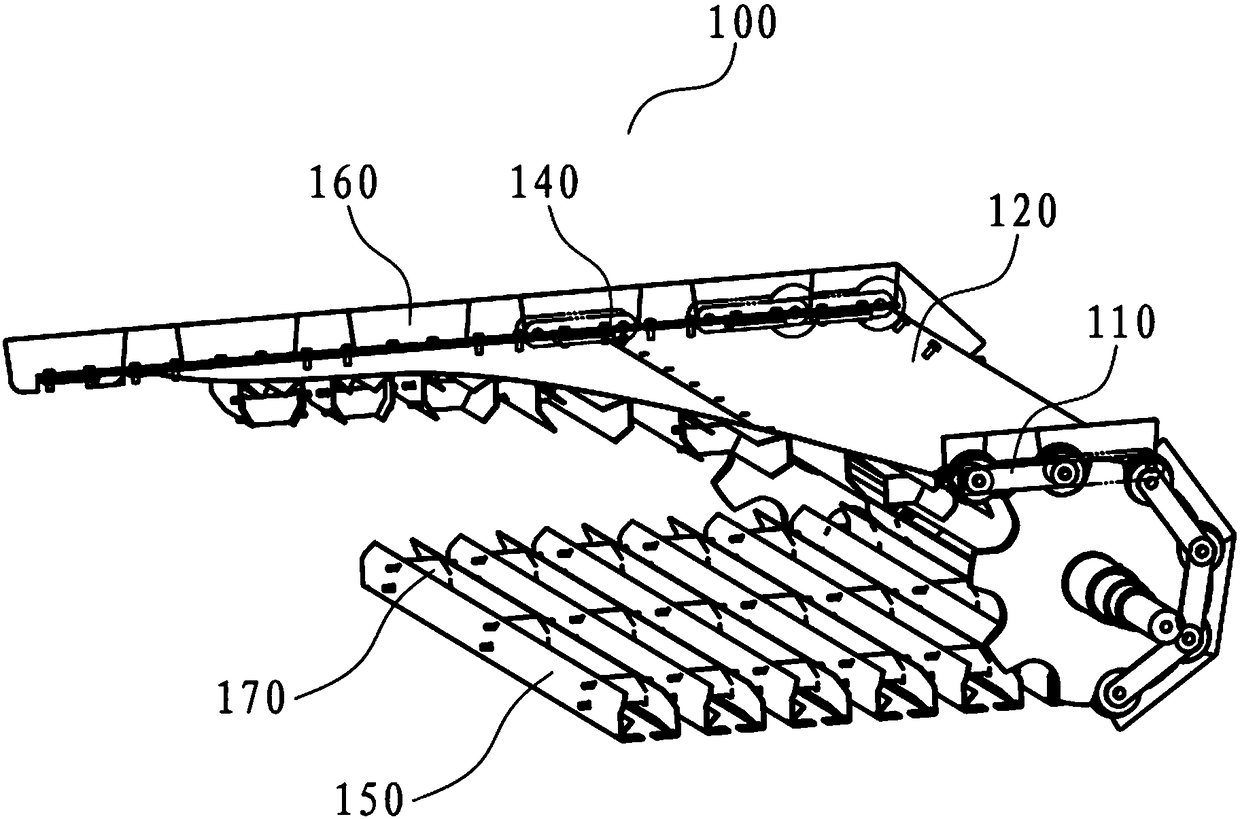
[0020] The conveying device 100 for the feed dryer of the present invention will be described in detail below in conjunction with the accompanying drawings. It should be noted that the accompanying drawings are only for illustration and should not be construed as limiting the present invention.

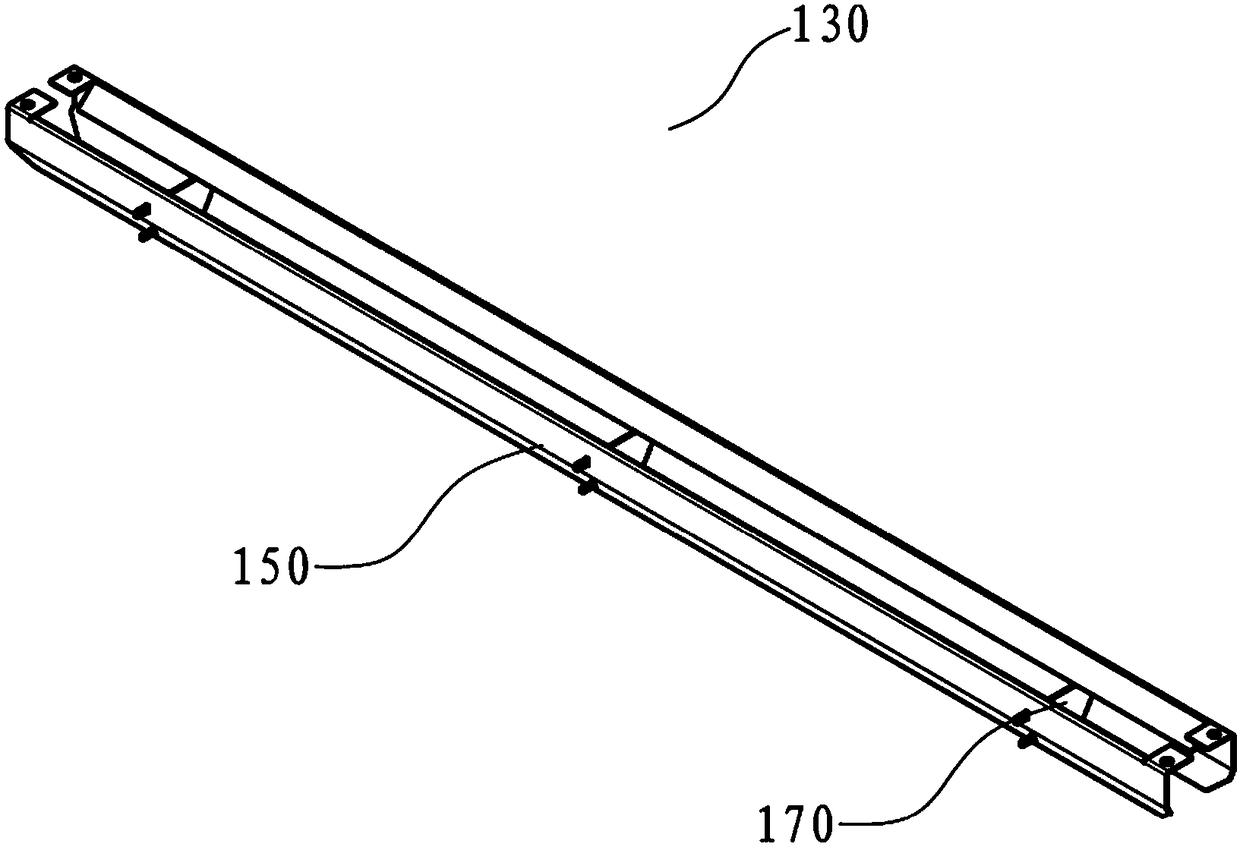
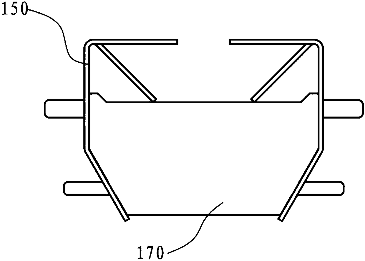
[0021] figure 1 Schematically shows the three-dimensional structural view of the support member 130 of the conveying device 100 for the feed dryer of the present invention, as figure 1 As shown, each supporting member 130 is composed of a pair of inverted V-shaped bent plates 150 and reinforcing ribs 170 . The length of the inverted V-shaped bent plate 150 used in actual production is equivalent to the width of the conveyor belt 120, so it has a relatively long length, and the reinforcing rib 170 here plays a role in fixing and preventing the reversed V-shaped bent plate 150 from twisting .

[0022] The two inverted V-shaped bent plates 150 of each support member 130 can have variou...


PUM


Abstract

The invention relates to a conveyor (100) for a feed drier. The conveyor comprises a pair of annular transmission chains (110), a conveyor belt (120) arranged between the transmission chains (110), and support parts (130) matched for chain knots (140) of the transmission chains (110). The transmission chains are arranged to be suitable for running synchronously under the drive of a drive device; multiple air holes are formed in the conveyor belt; each support part (130) is arranged between each pair of chain knots (140); two ends of each support part (130) and each pair of chain knots (140) are fixed together; and each support part (130) is provided with an inverted V-shaped bending plate (150) horizontally arranged in a conveying direction of each transmission chain, extending to a lowersurface of the conveyor belt (120) from bottom to top, and bending back from the position.

Description

technical field [0001] The invention relates to a conveying device, in particular to a conveying device for a feed dryer. Background technique [0002] The dryer is widely used in the production of aquatic feed and high-grade livestock and poultry feed. The main function is to dry the feed, control the water content of the feed, and directly affect the quality of the feed. The price of the equipment is relatively high, and it is one of the important feed equipment. Dryers at home and abroad mostly use sieve plates (perforated metal bending plates) as conveyor belts. Among them, multiple sieve plates are overlapped on the sides to form a continuous surrounding conveyor belt. The sieve plate is supported by a correspondingly continuously running support plate structure. Due to the low opening rate of the perforated sieve plate, it is not conducive to ventilation, resulting in uneven drying of the feed, high energy consumption, and frequent maintenance, which greatly reduces ...

Claims


Application Information

Patent Timeline
Patent Type & Authority Applications(China)
IPC IPC(8): B65G15/32B65G15/60F26B25/00
CPCF26B25/002B65G15/32B65G15/60
Inventor 何永溢骆建球曹楚能
Owner ANDRITZ CHINA
Learn More