Assembled prestressed truss for reinforcement and construction method thereof

A prestressed, prefabricated technology, applied in bridge reinforcement, erection/assembly of bridges, building maintenance, etc., can solve the problems of long interruption of traffic during construction period, complicated construction process, and increase of structural self-weight, etc., to achieve short construction period, The effect of clear force and reduction of prestress loss

Active Publication Date: 2018-06-22
CHANGSHA UNIVERSITY OF SCIENCE AND TECHNOLOGY
View PDF10 Cites 4 Cited by
  • Summary
  • Abstract
  • Description
  • Claims
  • Application Information

AI Technical Summary

Problems solved by technology

[0007] Aiming at some problems existing in the prior art, such as complicated construction technology, poor durability, long construction period and traffic interruption t

Method used


Image

  • Assembled prestressed truss for reinforcement and construction method thereof
  • Assembled prestressed truss for reinforcement and construction method thereof
  • Assembled prestressed truss for reinforcement and construction method thereof

Examples


Embodiment 1

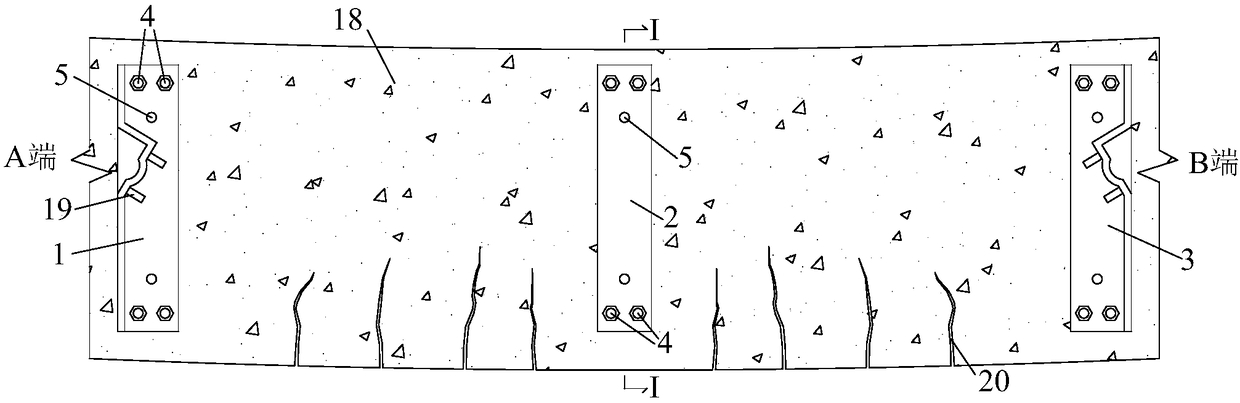
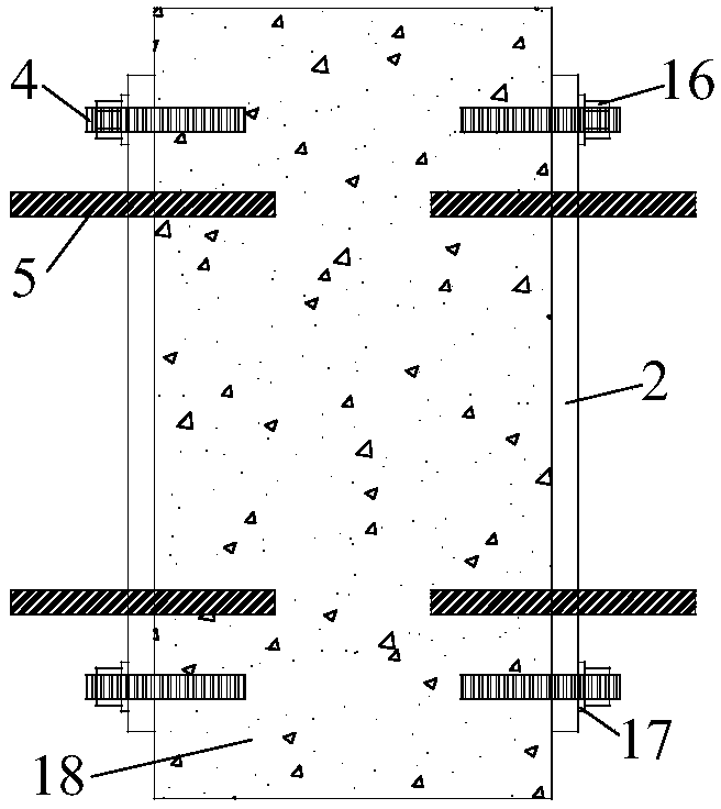
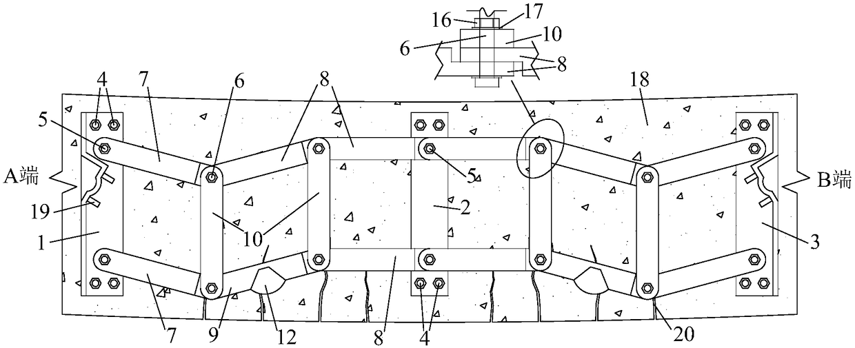
[0036] see Figure 1 to Figure 7 , This embodiment includes anchoring steel plates, A-end anchoring angle steel, B-end anchoring angle steel, upper chord, lower chord, web, anchorage and prestressed tendon. The anchor steel plate is fixed on the concrete member, and the anchor angle steel at the A end and the anchor angle steel at the B end are fixed on the concrete member symmetrically with the anchor steel plate as a symmetrical axis. The A-end anchor angle steel and the B-end anchor angle steel both include a bottom steel plate and a vertical steel plate. The A-end anchor angle steel and the B-end anchor angle steel used in this embodiment are symmetrical structures for the convenience of processing. In actual use, only It is necessary to ensure that the structure of the bottom steel plate and the vertical steel plate is used. One side of the bottom steel plate is in contact with the concrete member, and the vertical steel plate is vertically arranged on the surface of the...

Embodiment 2

[0053] see Figure 8 , the two ends of each slanting rod in this embodiment are also connected to the joints of the adjacent connecting rods in the upper chord and the lower chord, but the difference from Embodiment 1 is that each slanting rod in this embodiment is not They are connected end to end, but are arranged in parallel on both sides of the anchoring steel plate, and the two oblique rods connected to the anchoring steel plate share a joint. Other structures of this embodiment are the same as those of Embodiment 1.

[0054] The setting of the above slanting rods is only an example adopted in this embodiment. In actual use, as long as the two ends of each slanting rod are also connected to the joints of the adjacent connecting rods in the upper chord and the lower chord, the principle can be Correspondingly make the deformation of various arrangements.


PUM


Abstract

The invention discloses an assembled prestressed truss for reinforcement and a construction method thereof. The truss is composed of anchoring angle steel, an anchoring steel plate, a chord member, aweb member, prestressed tendons and anchors. The components of the truss are all prefabricated in a factory and assembled on site through bolts, and the prestressed tendons are anchored at both ends of a truss body. The truss body can be deformed in a prestressed tensioning process to ensure that a prestressing force is effectively applied to reinforced components to achieve the effects of reducing downward deflection and closing seams. After tensioning is completed, the truss body is fixed through inclined rods to enable the inclined rods to serve as force frameworks, the truss body bears bending moments and shear forces together with the components, the stiffness of the components is enhanced, meanwhile an anchoring system of the prestressed tendons is enhanced, and the effect of reducing the prestressing loss is achieved. The truss for reinforcement adopts an assembly concept, the construction is convenient, the traffic is not needed to be interrupted, large hoisting equipment is not needed, the construction period is short, and the advantages of two reinforcement methods of the truss and external prestressing are fully utilized. The truss has wide application in the field of concrete structure reinforcement.

Description

technical field [0001] The invention relates to the field of bridge and building structure reinforcement, in particular to an assembled prestressed truss for reinforcement and a construction method thereof. Background technique [0002] Due to its superior performance, concrete structures have been widely used in engineering practice. However, due to concrete aging, cracking, steel corrosion, defect grouting, overloading and other reasons, the existing concrete structures have insufficient bearing capacity and stiffness during the service period. Therefore, it is necessary to An efficient reinforcement method for strengthening structures. [0003] At present, the methods of strengthening concrete structures mainly include bonding steel reinforcement, pasting fiber composite reinforcement, external prestress reinforcement, and enlarging cross-section reinforcement. Although the reinforcement method of sticking steel and sticking fiber composite materials has a small increase...

Claims


Application Information

Patent Timeline
IPC IPC(8): E01D22/00E04G23/02
CPCE01D22/00E04G23/0218
Inventor 王磊吴兵辉张旭辉张建仁马亚飞
Owner CHANGSHA UNIVERSITY OF SCIENCE AND TECHNOLOGY
Why Eureka
Try Eureka