Air valve correct time-lift adjusting mechanism
A technology of adjusting mechanism and valve timing, which is applied in mechanical equipment, engine components, machines/engines, etc., can solve the problems of inability to adjust the valve timing and lift of the engine, and achieve the effect of easy promotion, convenient manufacture and emission reduction.
- Summary
- Abstract
- Description
- Claims
- Application Information
AI Technical Summary
Problems solved by technology
Method used
Image

Examples
Embodiment Construction
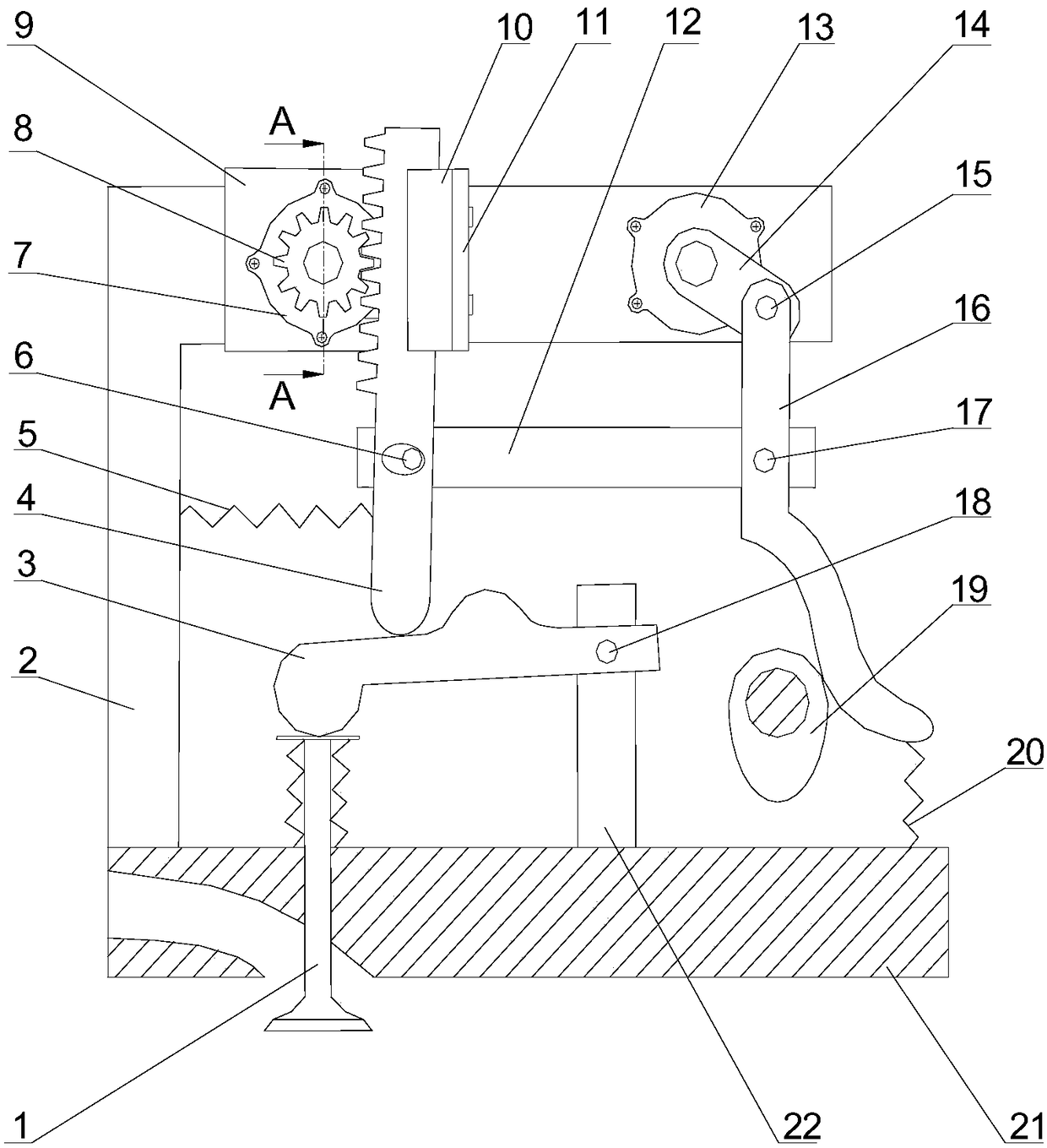
[0027] Attached below Figure 1-8 The present invention is described in detail:
[0028] refer to figure 1 , a valve timing-lift adjustment mechanism of the present invention comprises the following structures: valve (1), L-shaped bracket (2), swing arm (3), rack (4), return spring I (5) , pin a (6), stepping motor I (7), gear (8), connecting device (9), guide rail (10), connecting plate (11), connecting rod (12), stepping motor II (13) , rotating arm (14), pin b (15), hockey stick connecting rod (16), pin c (17), pin d (18), cam (19), return spring II (20), cylinder head (21) , swing arm support (22).
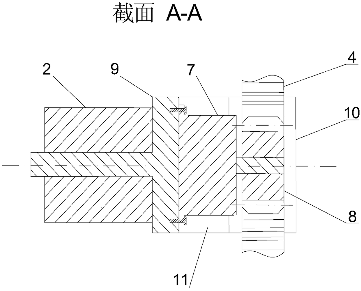
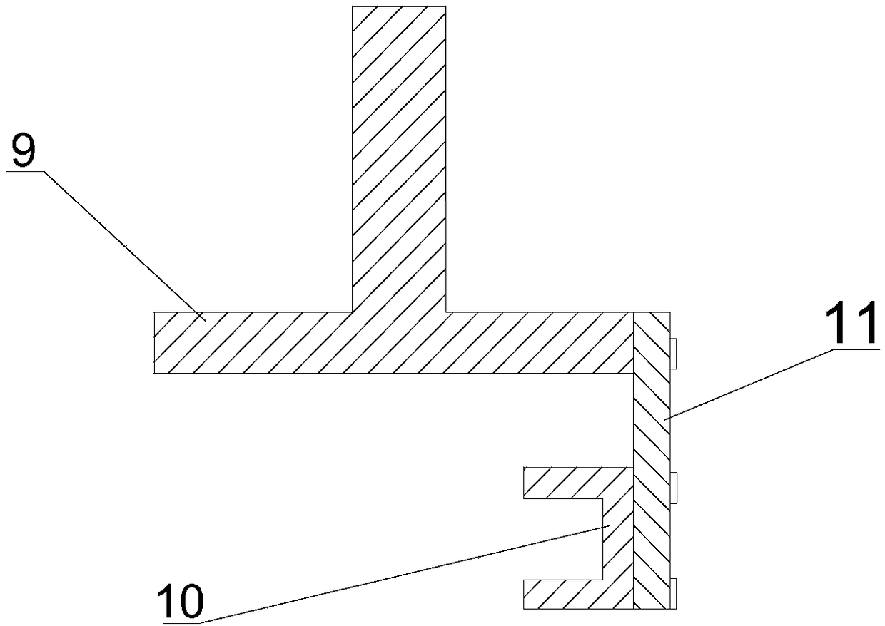
[0029] refer to figure 1 , figure 2 , Figure 4 , Figure 7 , the shaft (901) of the connecting device (9) is connected with the shaft hole (201) provided on the L-shaped bracket (2), and fits with its clearance, so that the connecting device (9) can rotate relative to the bracket (2); the rack ( 4) The upper part is placed between the guide rail (10) and the gear (8)...
PUM
 Abstract
Description
Claims
Application Information
 - Generate Ideas
- Intellectual Property
- Life Sciences
- Materials
- Tech Scout
- Unparalleled Data Quality
- Higher Quality Content
- 60% Fewer Hallucinations
Browse by: Latest US Patents, China's latest patents, Technical Efficacy Thesaurus, Application Domain, Technology Topic, Popular Technical Reports.
© 2025 PatSnap. All rights reserved.Legal|Privacy policy|Modern Slavery Act Transparency Statement|Sitemap|About US| Contact US: help@patsnap.com