Impulse current generator using vacuum switches to realize multiple return waves

A vacuum switch and inrush current technology, which is applied in the direction of instruments, measuring electricity, and measuring electrical variables, etc., can solve problems such as unreliability, limited influence, and malfunction discharge, and achieve the effects of simplified structure, stable operation, and simplified structure

Pending Publication Date: 2018-06-22
BEIJING HUATIAN MECHANICAL ELECTRICAL INST +1
View PDF0 Cites 3 Cited by
  • Summary
  • Abstract
  • Description
  • Claims
  • Application Information

AI Technical Summary

Problems solved by technology

exist figure 2 In the traditional multiple return shock wave impulse current generator shown, the resistances of the charging resistors R1, R2, ..., R(n-1), Rn are on the order of kΩ, and the wave-modulating impedances Z1, Z2, ..., Z(n- 1) The resistance of Zn is on the order of mΩ, so the discharge ball gaps G2, ..., G(n-1), and Gn sequentially trigger the discharge to have a relatively limited impact on the remaining undischarged capacitor banks, thus producing figure 1 The multi-pulse discharge current shown
[0006] The problem with the traditional multiple return shock wave impulse current generator is that the structure of the three-electrode high-voltage discharge ball gaps G1, G2, ..., G(n-1), and Gn is complex, and each pair of discharge ball gaps must have a set of ball gap adjustment. The transmission mechanism requires a set of measuring devices for the size of the ball gap, as well as a trigger pulse amplifier for the three-electrode discharge ball gap
If the size of the ball gap is not adjusted properly, during the charging process, some discharge ball gaps may malfunction and discharge before being triggered; -1) When Gn is triggered, due to the rise of ground potential and electromagnetic interference caused by the large current pulse discharge circuit, self-discharge or non-discharge faults may occur between the ball gaps, thus making the operation of the impulse current generator unstable , unreliable, leading to test failure

Method used


Image

  • Impulse current generator using vacuum switches to realize multiple return waves
  • Impulse current generator using vacuum switches to realize multiple return waves
  • Impulse current generator using vacuum switches to realize multiple return waves

Examples


Embodiment

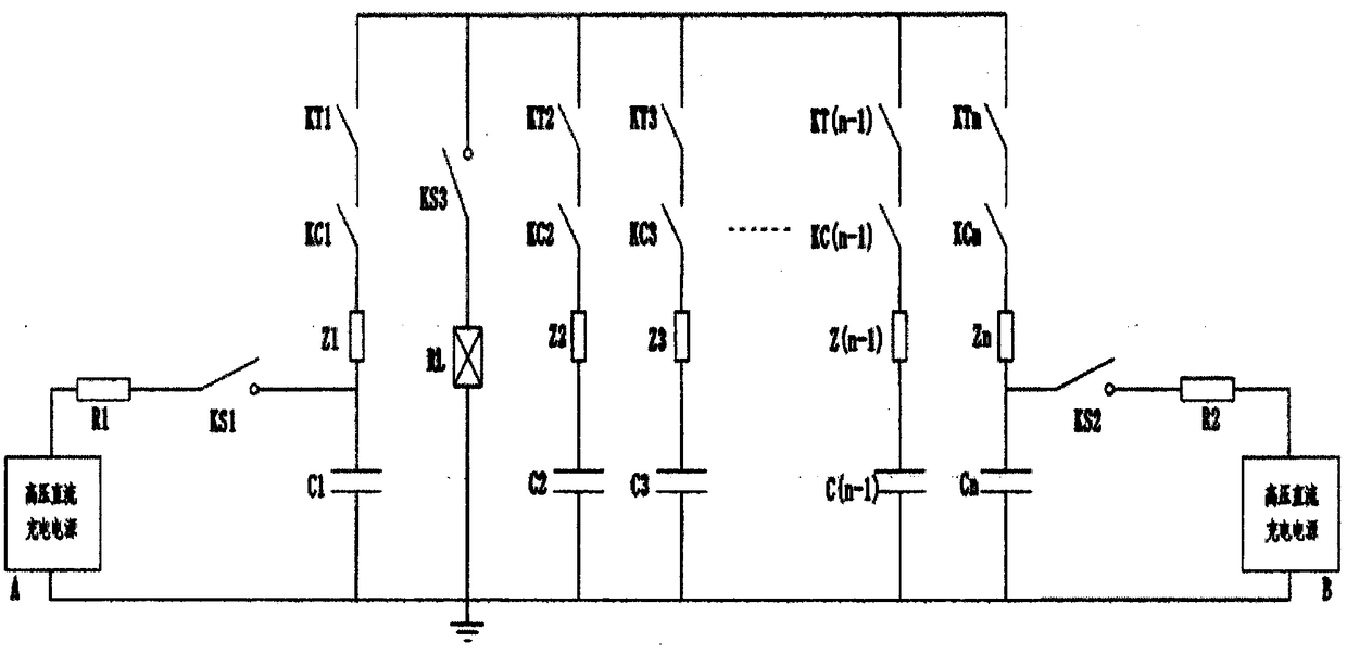
[0022] Example: such as image 3 , after the high-voltage DC charging power supply A is connected in series with the charging resistor R1, it is connected in series with the isolating switch KS1 to charge the capacitor bank C1. After the high-voltage pole outlet of the capacitor group C1 is connected in series with the wave-modulating impedance Z1, the vacuum switches KC1 and KT1 are connected in sequence, and one pole of the vacuum switch KT1 is connected with one pole of the isolating switch KS3. After the high-voltage pole outlet of the capacitor group C2 is connected in series with the modulating impedance Z2, then connect the vacuum switches KC2 and KT2 in sequence; after the high-voltage pole outlet of the capacitor group C3 is connected in series with the modulating impedance Z3, then connect the vacuum switches KC3 and KT3 in sequence; ...; After the high-voltage pole outlet of the capacitor group C(n-1) is connected in series with the wave-modulating impedance Z(n-1),...


PUM


Abstract

The invention particularly relates to a multi-pulse impulse current generator using vacuum switches to realize multiple return waves. The multi-pulse impulse current generator comprises two high-voltage direct current charging power supplies, two charging resistors, three isolating switches, a number of capacitor banks, a number of vacuum switches and wave modulating impedance. A number of vacuumswitches are used to replace a three-electrode high-voltage discharge ball gap. A transmission mechanism for adjusting the three-electrode ball gap, a device for measuring the size of the ball gap, and a pulse amplifier for triggering the three-electrode discharge ball gap are eliminated. Three isolating switches and a number of vacuum switches are used to switch the charging and discharging circuits of the multi-pulse impulse current generator. A large number of charging resistors are omitted. The structure of the system is simplified. The stability and reliability of the operation of the multi-pulse impulse current generator are improved. The multi-pulse impulse current generator can be applied in the fields of aircraft lightning effect test and the electrical performance test of surge protectors.

Description

technical field [0001] The invention relates to the fields of aircraft lightning test and surge protector test, in particular to a multi-pulse impulse current generator which adopts a vacuum switch to realize multiple return shock waves. Background technique [0002] Lightning is a natural phenomenon of gas discharge in nature, and its direct and indirect effects have greatly affected people's production and life. In order to prevent the impact of lightning on various electrical products, people have conducted a lot of research on lightning phenomena, and formulated a variety of waveform standards for lightning protection tests. The SAE ARP 5412 lightning environment and related test waveforms formulated by the American Society of Automotive Engineers (SAE) and the ED (EUROCAE Documents) series of standards ED-84 lightning environment and related test waveforms issued by the European Civil Aviation Equipment Organization stipulate multiple return strikes Wave (Multiple stro...

Claims


Application Information

Patent Timeline
Patent Type & Authority Applications(China)
IPC IPC(8): G01R1/30
CPCG01R1/30
Inventor 李军科艾晓宇周佳安敬然
Owner BEIJING HUATIAN MECHANICAL ELECTRICAL INST
Why Eureka
Try Eureka