Laser positioning device

A technology for laser positioning and measuring beams, which is applied in measuring devices, re-radiation of electromagnetic waves, and utilization of re-radiation, etc. It can solve problems such as tediousness, poor user experience, and large errors

Pending Publication Date: 2018-06-22
NORTHWEST INSTR SHANGHAI +1
View PDF0 Cites 14 Cited by
  • Summary
  • Abstract
  • Description
  • Claims
  • Application Information

AI Technical Summary

Problems solved by technology

However, the auxiliary measurement of the horizontal bubble can only be measured when the horizontal bubble is adjusted to the center state, so it is prone to problems such as slow debugging, easy vibration of the horizontal bubble, and cumbersome operation.
That is to say, the traditional laser rangefinder basically performs distance measurement and positioning after the laser rangefinder is basically horizontal or vertical by manual visual inspection, or performs measurement after calibration by other calibration devices. These operations are cumbersome and cause large The error makes the user experience relatively poor

Method used


Image

  • Laser positioning device
  • Laser positioning device
  • Laser positioning device

Examples


Embodiment 1

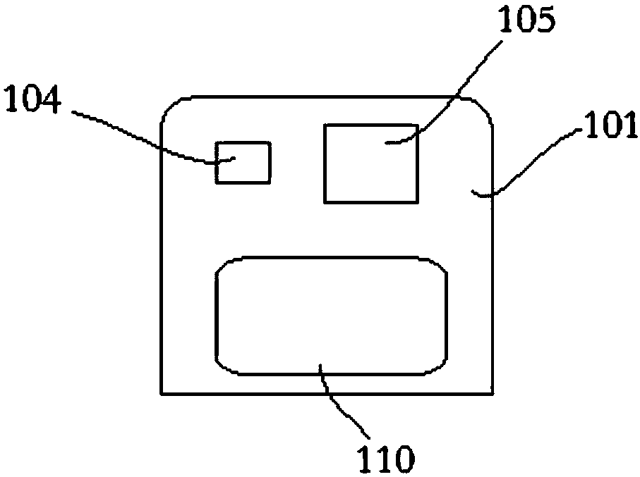
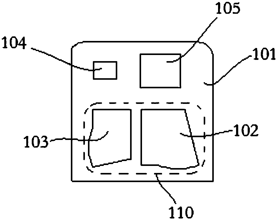
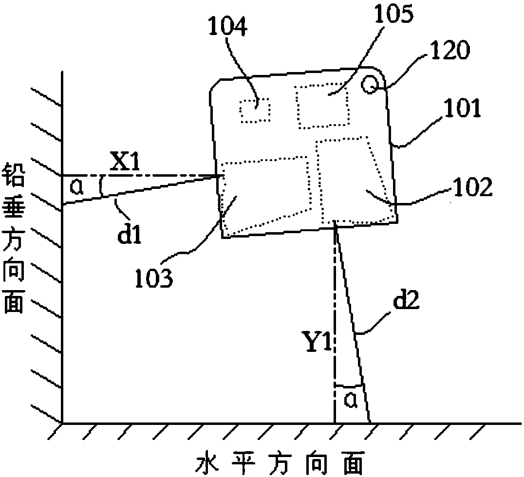
[0025] according to figure 2 , image 3 Embodiment 1 of the present embodiment shown, in this embodiment, the laser positioning device 101 includes a ranging unit 110, an acceleration sensing unit 104, and a control unit 105; wherein, the ranging unit 110 includes a first A ranging module 102 and a second ranging module 103 . In this embodiment, the first ranging module 102 is used to emit and receive the first measuring beam on the horizontal plane in the target space, so as to measure the distance to the actual irradiation point on the horizontal plane; the second ranging module 103 The second measuring light beam is used to transmit and receive the second measuring beam on the vertical plane in the target space, so as to measure the distance to the actual irradiated point on the vertical plane. In addition, in this embodiment, the included angle between the first measuring beam and the second measuring beam is set as a fixed angle.

[0026] Such as figure 2 , image ...

Embodiment 2

[0031]In this embodiment, the laser positioning device 101 includes a ranging unit 110, an acceleration sensing unit 104, and a control unit 105; wherein, the ranging unit 110 includes a laser emitting module, a light splitting module, and a laser receiving and measuring module (attached Not shown in the figure) the laser emitting module and the laser receiving and measuring module.

[0032] The specific working principle of embodiment 2 is as follows:

[0033] Place the laser positioning device 101 in a substantially horizontal or substantially vertical state in the target space, the laser emitting module of the distance measuring unit 110 emits a beam, and the beam splitting module divides the beam emitted by the laser emitting module into the first horizontal plane in the target space. The measurement beam and the second measurement beam to the vertical direction plane in the target space, the laser receiving and measuring module receives the first measurement beam and the ...

Embodiment 3

[0036] In this embodiment, the laser positioning device 101 includes a ranging unit 110, an acceleration sensing unit 104, and a control unit 105; wherein, the ranging unit 110 includes a laser transceiver measurement module, a spectroscopic module (both in the drawings Not shown) laser transceiver measurement module.

[0037] The specific working principle of embodiment 3 is as follows:

[0038] Place the laser positioning device 101 in a substantially horizontal or substantially vertical state in the target space, the laser transceiver and measurement module of the distance measuring unit 110 emits light beams, and the beam splitting module divides the beam emitted by the laser transceiver and measurement module into horizontal planes in the target space. The first measurement beam and the second measurement beam to the vertical direction plane in the target space, the laser transceiver measurement module receives the first measurement beam and the second measurement beam to...


PUM


Abstract

The invention discloses a laser positioning device, which comprises a distance measuring unit, an acceleration sensing unit and a control unit. Wherein the distance measuring unit measures the distance between the actual irradiation point of the laser positioning device in the target space to the horizontal direction and the distance to the actual irradiation point on the vertical direction respectively; the acceleration sensing unit measures the current acceleration direction of the laser positioning device; the control unit calculates an angle deviation between the current acceleration direction and the gravity direction of the distance measuring unit in the current direction, and calculates the positioning coordinates of the laser positioning device in the target space by using the measured distance to actual irradiation point on the horizontal direction and the distance to actual irradiation point on the vertical direction. By obtaining the accuracy compensation of the distance from the horizontal direction surface and/or the vertical distance to the vertical direction surface, the invention realizes the quick and accurate positioning of the target object in the target space, and improves the operational reliability and precision of the device.

Description

technical field [0001] The invention relates to the technical field of space positioning, in particular to a laser positioning device. Background technique [0002] As a distance measuring instrument, the laser rangefinder is mostly used in construction projects. The laser range finder in the prior art performs distance measurement through pulse or phase, which first measures two target points and then obtains the vertical distance between the two points on the measured object surface through a default fixed algorithm, and obtains the laser range finder and The vertical distance to the target surface can only be measured with visual aiming or with auxiliary accessories. However, the measurement accuracy of visual aiming is poor, which leads to inaccurate and convenient positioning measurement; and the auxiliary measurement process of accessories is more cumbersome, which makes the measurement not convenient and also increases the error in the measurement. [0003] In order...

Claims


Application Information

Patent Timeline
Patent Type & Authority Applications(China)
IPC IPC(8): G01S17/08G01S7/481
CPCG01S7/481G01S17/08
Inventor 李忠山石昕邢星
Owner NORTHWEST INSTR SHANGHAI
Why Eureka
Try Eureka