Cable fixer with high adaptability

An adaptable and fixer technology, applied in the direction of electrical components, can solve problems such as poor fixing effect and easy loosening of cable ducts, and achieve the effect of changing the internal space

Pending Publication Date: 2018-06-22
苏州贝弗金属科技有限公司
View PDF0 Cites 0 Cited by
  • Summary
  • Abstract
  • Description
  • Claims
  • Application Information

AI Technical Summary

Problems solved by technology

[0003] Existing cable duct fixers usually need to match the diameter of the cable duct. Once the diameter of the cable duct is small, the fixing effect is poor and the cable duct is easy to loosen

Method used


Image

  • Cable fixer with high adaptability
  • Cable fixer with high adaptability

Examples


Embodiment

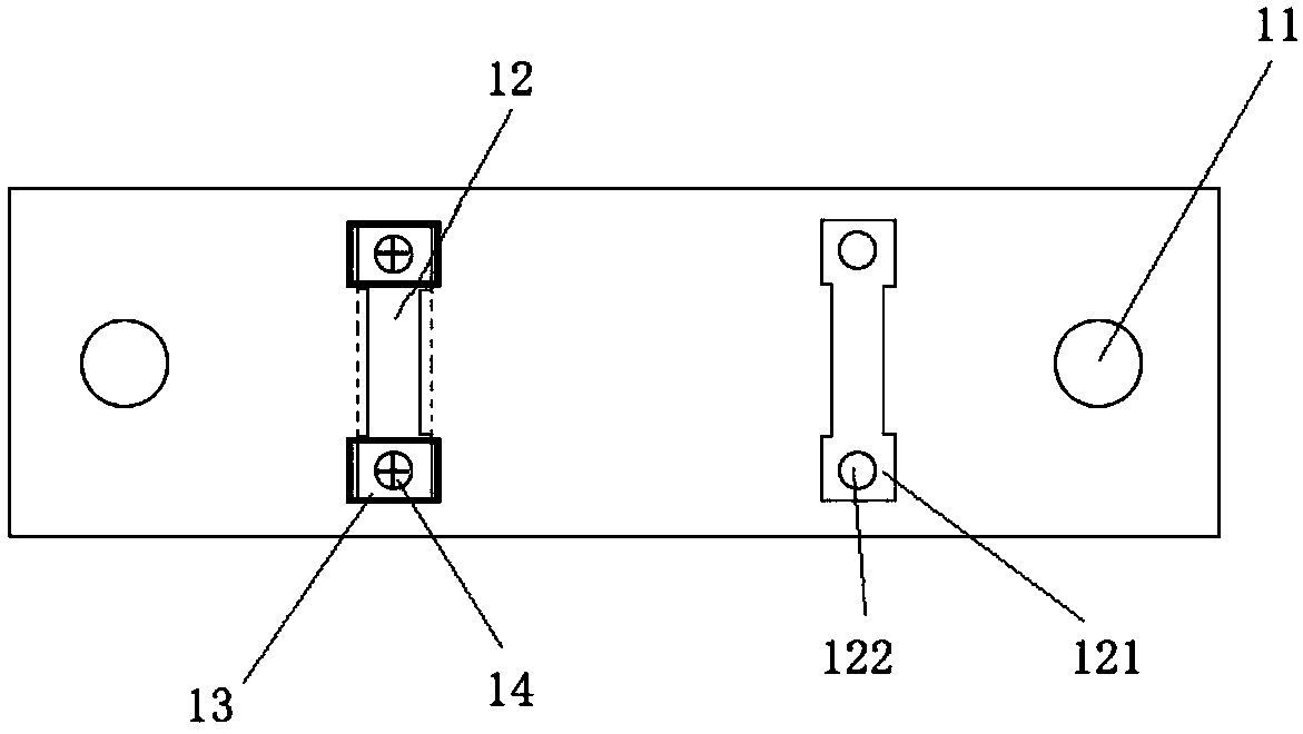
[0024] This embodiment provides a highly adaptable cable holder, such as figure 1 and 2 shown, including:

[0025] The base 1 includes mounting holes 11 on both sides (usually also screw holes, used to fix the base 1 to the wall and other objects through expansion screws), at least one mounting groove 12 in the middle (the opening width of the mounting groove 12 is smaller than that of the groove The width of the inner part can also be a trapezoidal groove or a T-shaped groove). A screw hole 122 is provided at the end 121, a fixing block 13 is arranged in the entry end 121, and the fixing block 13 is fixed by a screw 14 extending into the screw hole 122;

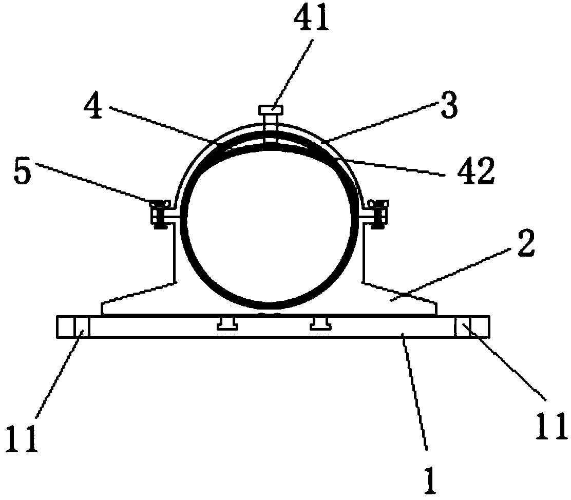
[0026] The lower fixing seat 2 is arranged on the base 1 and has a semicircular inner wall, and the bottom has a protrusion that can enter the trapezoidal groove 12 from the entry end 121;

[0027] The upper fixing base 3 has a semicircular inner wall, and the upper fixing base 3 and the lower fixing base 2 form a complet...


PUM


Abstract

The invention relates to a cable fixer with high adaptability. The relative position of the lower fixed seat and the base can be adjusted by changing the position of the convex block in the installation slot through the cooperation of the base with the convex block on the lower fixed seat Meanwhile, the movable inner wall in the fixed seat can stretch into the inside when the screw is screwed, sothat the inner space of the fixed seat is changed, so that the cable with the diameter smaller than the fixer is fixed.

Description

technical field [0001] The invention relates to a highly adaptable cable fixer, which belongs to the technical field of metal products. Background technique [0002] The cable holder is a kind of fixing device that fixes the cable duct on the wall. The cable holder is first installed on the wall, and then the cable duct passes through the circular fixing cavity in the middle of the cable holder, so that the cable duct is fixed. The support is fixed. [0003] The existing cable duct fixer usually needs to match the diameter of the cable duct. Once the diameter of the cable duct is small, the fixing effect is poor and the cable duct is easy to loosen. Contents of the invention [0004] The object of the present invention is to provide a cable holder with simple installation and high adaptability. [0005] In order to achieve the above object, the technical scheme adopted in the present invention is: [0006] The present invention provides a highly adaptable cable holder, ...

Claims


Application Information

Patent Timeline
IPC IPC(8): H02G3/30H02G3/02
CPCH02G3/02H02G3/30
Inventor 裴黎荣冯淦杨阳
Owner 苏州贝弗金属科技有限公司
Why Eureka
Try Eureka