
Compound surge protector and compound surge protection method therefor

A surge protector, composite technology, applied in emergency protection circuit devices, emergency protection circuit devices for limiting overcurrent/overvoltage, electrical components, etc., to achieve the effect of stable triggering and large triggering energy

Pending Publication Date: 2018-06-22
广东立信防雷科技有限公司
View PDF7 Cites 0 Cited by
  • Summary
  • Abstract
  • Description
  • Claims
  • Application Information

AI Technical Summary

Problems solved by technology

[0003] However, in higher voltage power distribution systems such as new energy or industrial power, such as 690VAC, 760VAC, 960VAC, etc., due to the lack of directly adaptable high-voltage, high-energy lightning protection components, the gap protection of the 380VAC system is still used Most of the basic components currently used are in the form of superposition. Of course, this kind of superposition is not a direct accumulation in a simple sense. It must consider its overall response time to lightning surges (or other surge pulses) and the energy coordination of the discharge channel.

Method used


Image

  • Compound surge protector and compound surge protection method therefor
  • Compound surge protector and compound surge protection method therefor
  • Compound surge protector and compound surge protection method therefor

Examples


Embodiment 1

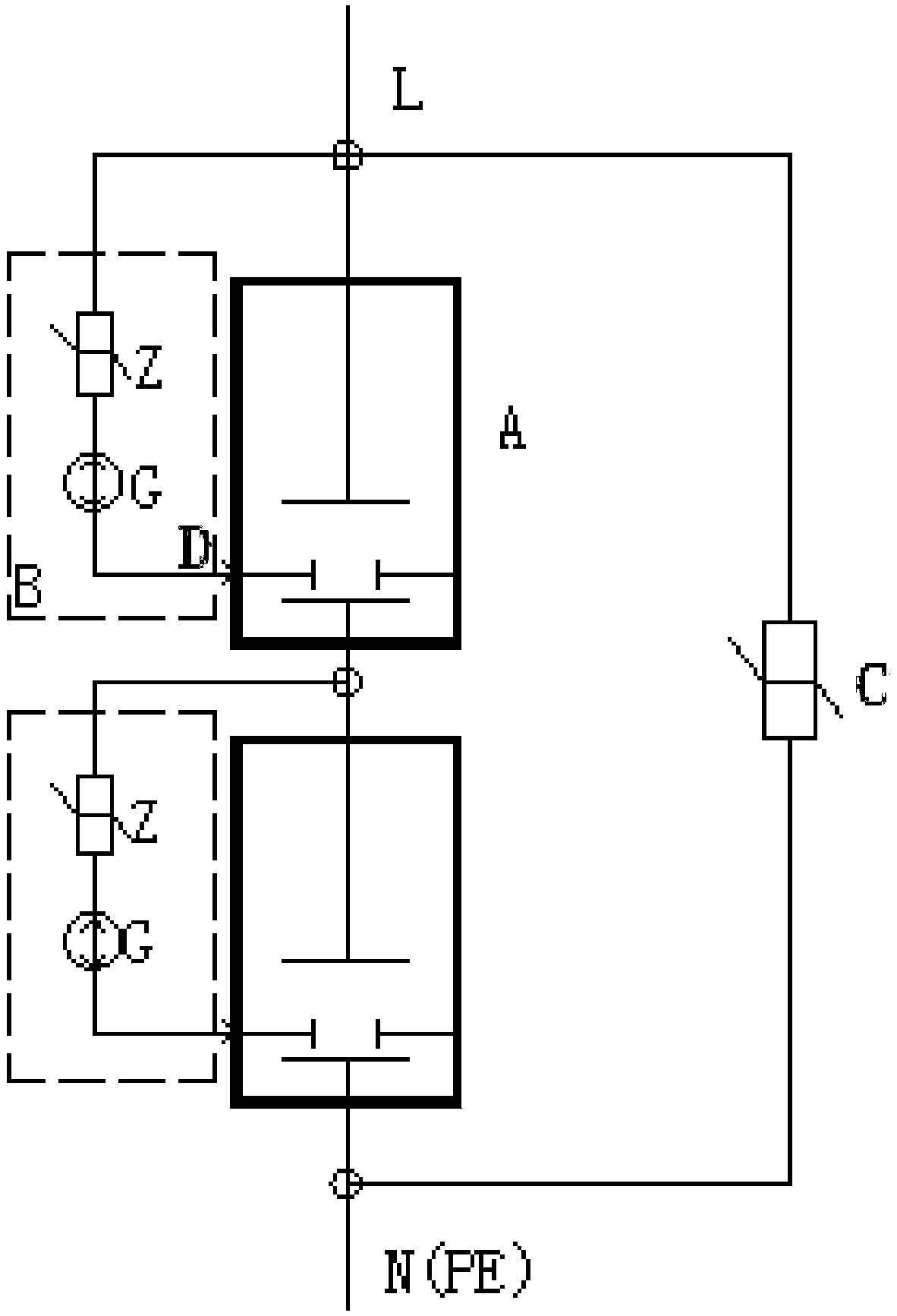
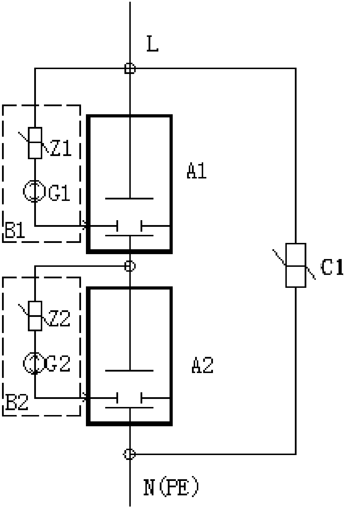
[0025] see figure 1 , the composite surge protector of the low-voltage power distribution system of the present invention, which includes a piezoresistor C, at least two three-pole discharge gap bodies A, and at least two triggers corresponding to at least two three-pole discharge gap bodies A Circuit B. Each three-pole discharge gap body A has a positive electrode L, a negative electrode N and a trigger electrode D.

[0026] Each trigger circuit B includes a piezoresistor Z and a discharge tube G. All the three-pole discharge gap bodies A are connected in series through the positive electrode L and the negative electrode N to form a three-pole discharge gap body assembly, and the positive electrode L of the first three-pole discharge gap body A is electrically connected to the L line of the low-voltage power distribution system, and the last The negative electrode N electrode of the three-pole discharge gap body A.

[0027] Connect the N(PE) line of the low-voltage power d...

Embodiment 2

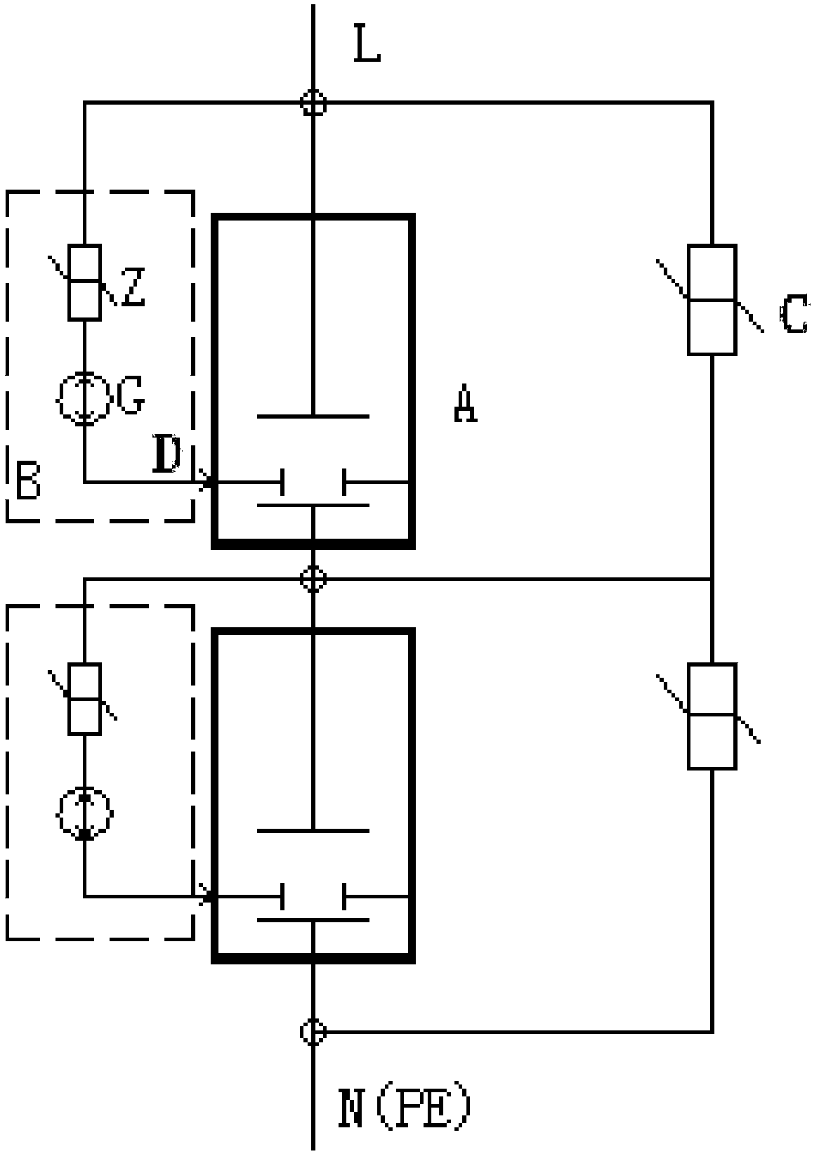
[0041] see image 3 The composite surge protector of the low-voltage power distribution system of the present invention may also include at least two piezoresistors C, at least two three-pole discharge gap bodies A, and at least two three-pole discharge gap bodies A corresponding to at least two Two trigger circuits B. Each three-pole discharge gap body A has a positive electrode L, a negative electrode N and a trigger electrode D. Each trigger circuit B includes a piezoresistor Z and a discharge tube G.

[0042] All the three-pole discharge gap bodies A are connected in series through the positive electrode L and the negative electrode N to form a three-pole discharge gap body assembly, and the positive electrode L of the first three-pole discharge gap body A is electrically connected to the L line of the low-voltage power distribution system, and the last The negative electrode N of the three-pole discharge gap body A is electrically connected to the N(PE) line of the low-...


PUM


Abstract

The invention discloses a compound surge protector and a compound surge protection method therefor. The surge protector comprises a piezoresistor C, at least two three-pole discharge gap bodies, and at least two trigger circuits corresponding to the at least two three-pole discharge gap bodies, wherein each trigger circuit comprises a piezoresistor Z and a discharge tube. All three-pole dischargegap bodies are connected through positive electrodes and negative electrodes in series to form a three-pole discharge gap body component; the positive electrode of the first three-pole discharge gap body is connected with an L line of a low-voltage power distribution system; the negative electrode of the three-pole discharge gap body at the end is connected with an N (PE) line of the low-voltage power distribution system; and a trigger electrode of each three-pole discharge gap body is connected to the positive electrode through the corresponding discharge tube and piezoresistor Z; and the piezoresistor C is connected with the three-pole discharge gap body component in parallel. The surge protector disclosed by the invention is stable in triggering and high in trigger energy, and can adaptto lightning protection of new energy and industrial power distribution systems of which rated voltage is greater than 690VAC.

Description

technical field [0001] The invention relates to a surge protector and a surge protection method, in particular to a composite surge protector and a composite surge protector. Background technique [0002] In the basic components of the surge protector in the low-voltage power distribution system (380VAC), the turn-on response time of the varistor (MOV) is 25ns, and the nominal discharge current IN of a single varistor chip does not exceed 60KA (8 / 20us at most) ), the impulse current does not exceed Iimp = 5KA (10 / 350us); the conduction response time of the gap element is greater than 100ns, and the conduction current of a single gap is large, which can reach the nominal discharge current IN = 200KA (8 / 20us), the impulse current Im = 50KA (10 / 350us). The patent document with the patent number ZL201410651822.6 and the patent name "A Three-pole Discharge Gap Body and Its Discharge Trigger Circuit" discloses a discharge gap structure suitable for a 380V power supply system, and...

Claims


Application Information

Patent Timeline
Patent Type & Authority Applications(China)
IPC IPC(8): H02H9/06H02H9/04
CPCH02H9/04H02H9/06
Inventor 潘叶镜何锡华张丽陈伟
Owner 广东立信防雷科技有限公司
Learn More