FPGA-based micro-illumination control method for programmable LED array

An LED array and lighting control technology, applied in microscopes, lighting devices, instruments, etc., can solve problems such as increasing production costs, increasing control complexity, and difficulty in programmable LED arrays, reducing computing time, saving communication bandwidth, Avoid the effects of heavy use

Active Publication Date: 2018-06-22
NANJING UNIV OF SCI & TECH
View PDF5 Cites 14 Cited by
  • Summary
  • Abstract
  • Description
  • Claims
  • Application Information

AI Technical Summary

Problems solved by technology

However, whether it is stored in a non-volatile storage medium in advance or stored in a volatile storage medium during power-on initialization, an additional large-capacity storage medium (201310229029.2) is required, which increases the complexity of control and also increased production costs
Moreover, when stored in a volatile storage medium, a certain amount of initialization time will be required for each power-on initialization
In short, under the condition of using a small amount of limited hardware resources and data transmission bandwidth, how to realize the high-speed display of arbitrary color patterns by programmable LED arrays is a technical problem.

Method used


Image

  • FPGA-based micro-illumination control method for programmable LED array
  • FPGA-based micro-illumination control method for programmable LED array
  • FPGA-based micro-illumination control method for programmable LED array

Examples


Embodiment Construction

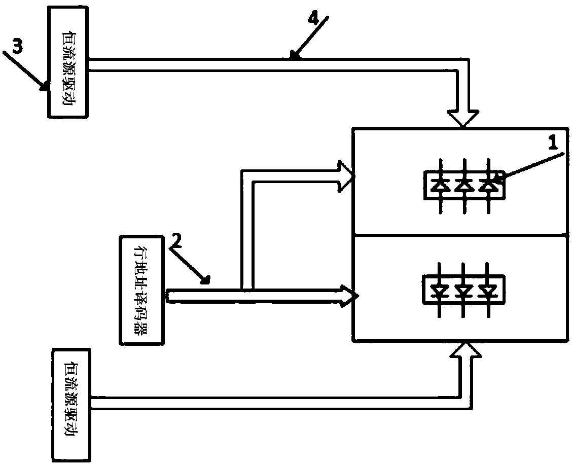
[0022] The FPGA-based programmable LED array microscopic illumination control method of the present invention uses a programmable LED array that drives multi-row scanning in parallel. combine figure 1 , The programmable LED array mainly includes programmable LED pixel 1, row address decoding 2, constant current source driver 3, a programmable LED pixel 1 includes three LED units R (red), G (green), and B (blue) , each pixel row is regarded as three parallel independent rows of R, G, and B; row address decoding 2 respectively drives two independent pixel rows, and these two pixel rows are respectively driven by different constant current sources 3; The source drives the three channels R, G, and B in parallel. figure 1 The programmable LED array can refresh two rows of LED pixel rows at a time, and the driving data of RGB programmable LED units in each column can be received at the same time, and the FPGA can be used to send two rows of RGB three-channel data synchronously at t...


PUM


Abstract

The invention discloses an FPGA-based micro-illumination control method for a programmable LED array. The method comprises the steps of firstly carrying out FPGA-based serial port receiving and decoding circuit design; calculating basic data of graphics for programmable LED array display on site according to a control instruction and carrying out circle area determining, in-circle brightness standard normal distribution and color area division and then classifying and storing the data into on-chip dual-port RAMs of an FPGA; reading out display data in the on-chip dual-port RAMs of the FPGA according to a scanning position of the programmable LED array; and finally quickly driving the programmable LED array, of using multi-row scanning, with separate three RGB channels in parallel by usingthe FPGA and displaying output data. According to the FPGA-based micro-illumination control method for the programmable LED array, a large number of external storage devices are saved, the programmable LED array is driven by using the FPGA, and graphic display and PWM modulation of drive current are achieved.

Description

technical field [0001] The invention belongs to the technical field of programmable LED array control, in particular to an FPGA-based programmable LED array micro-illumination control method with low transmission bandwidth and low complexity control. Background technique [0002] Multi-mode microscopic imaging uses the "label-free sample" imaging method to perform microscopic imaging of cell samples without fluorescent powder or dye labeling, avoiding the impact on cell activity caused by "labeling" in traditional microscopic observation. There are generally two ways to achieve multi-mode microscopic imaging. One is to directly use a programmable lighting source, such as a programmable LED array, to control it to display multiple lighting patterns of different colors to achieve multi-mode microscopic imaging. The other is to introduce a light source modulation device at the lighting end, such as a programmable LCD, through which to adjust lighting parameters such as light so...

Claims


Application Information

Patent Timeline
Patent Type & Authority Applications(China)
IPC IPC(8): H05B33/08H05B37/02G02B21/06H05B44/00
CPCG02B21/06H05B45/10H05B45/20H05B47/175
Inventor 左超潘向鹏陈钱孙佳嵩冯世杰张玉珍顾国华李加基范瑶丁君义尹维顾莹
Owner NANJING UNIV OF SCI & TECH
Why Eureka
Try Eureka