
Heat collecting end and heat radiating device

A technology of heat collection end and heat dissipation device, which is applied in cooling/ventilation/heating transformation, instruments, electrical and digital data processing, etc.

Pending Publication Date: 2018-06-22
TSINGHUA UNIV
View PDF0 Cites 0 Cited by
  • Summary
  • Abstract
  • Description
  • Claims
  • Application Information

AI Technical Summary

Problems solved by technology

[0004] Based on this, it is necessary to provide a heat collector and heat dissipation device for the problem that the heat dissipation coefficient of the radiator in the direction of fluid flow is continuously reduced, and the radiator has a large temperature difference in the direction of fluid flow.

Method used


Image

  • Heat collecting end and heat radiating device
  • Heat collecting end and heat radiating device
  • Heat collecting end and heat radiating device

Examples


Embodiment Construction

[0026] In order to make the purpose, technical solution and advantages of the present application clearer, the heat collecting end and the cooling device of the present application will be further described in detail through the following embodiments and in conjunction with the accompanying drawings. It should be understood that the specific embodiments described here are only used to explain the present application, not to limit the present application.

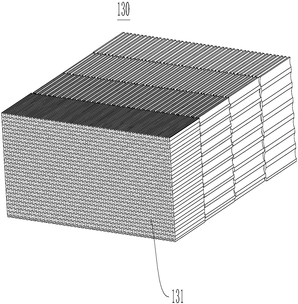
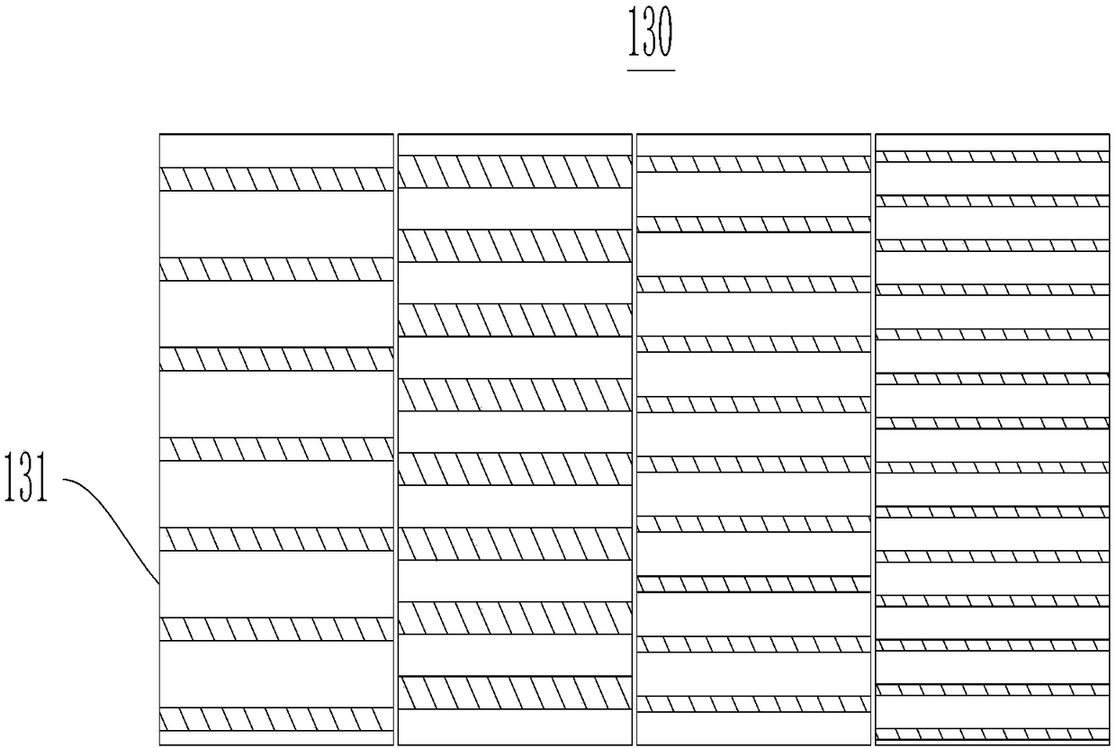
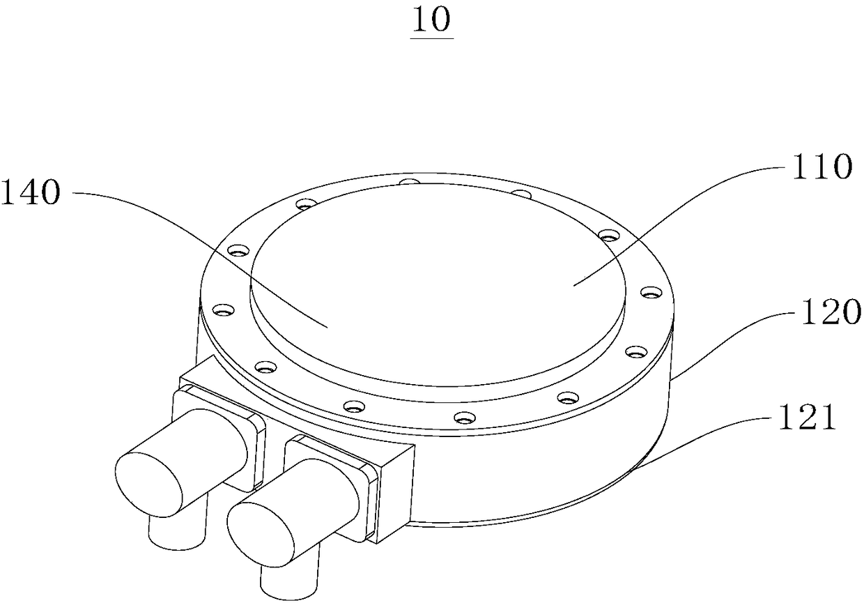
[0027] Please see attached Figure 1-3 , the present application provides a heat collection end 10 , and the heat collection end 10 includes at least two microchannel modules 130 . The at least two microchannel modules 130 have channels 131 extending along a first direction. The at least two microchannel modules 130 are arranged at intervals along the first direction. The pore diameter of the microchannel module 131 is 0 micron-1000 micron. The pore diameters of the channels 131 of the microchannel module 130 gradually de...


PUM

PropertyMeasurementUnit
Apertureaaaaaaaaaa
Lengthaaaaaaaaaa

Abstract

The application relates to a heat collecting end and heat radiating device, wherein the heat collecting end comprises at least two micro-channel modules set along the first direction, which is provided with a plurality of channel, the aperture of the said channel is 0 microns 1000 microns, the apertures of the channels of the said micro-channel modules decreasing along the first direction gradient, and the apertures of the channels of the adjacent micro-channel modules is 50 microns 150 microns.

Description

technical field [0001] The present application relates to a heat dissipation device, in particular to a heat collecting end and a heat dissipation device. Background technique [0002] In recent years, the integration and performance of electronic devices have been continuously improved, and the heat flux generated during operation has also been continuously increased, while the cooling space has been continuously reduced. If the heat generated by electronic devices cannot be removed in time, the temperature of the device will rise and affect its normal operation. How to efficiently and safely dissipate heat from chips has become one of the important topics in the research of electronic devices. [0003] At present, most of the commercially available heat sinks are single-layer fin-type micro-channels, which have a large pressure drop and require high-power pumps to match them. At the same time, the temperature of the fluid continues to rise during the process of flowing th...

Claims


Application Information

Patent Timeline
IPC IPC(8): H05K7/20G06F1/20
CPCH05K7/20272G06F1/20
Inventor 刘源贾星光张华伟李言祥
Owner TSINGHUA UNIV
Learn More