Gas power device for part cleaning machine

A technology of gas power and cleaning machine, which is applied in the direction of liquid cleaning method, cleaning method and utensils, chemical instruments and methods, etc. It can solve the problems of increasing transmission distance, economic loss, hidden danger of motor safety, etc., and achieves a high degree of integration , unified power source, good braking performance

Pending Publication Date: 2018-06-26
XIHUA UNIV
View PDF11 Cites 2 Cited by
  • Summary
  • Abstract
  • Description
  • Claims
  • Application Information

AI Technical Summary

Problems solved by technology

[0002] Existing parts cleaning machines generally use motors as the power source for their rotation, flipping, and translation; since the cleaning fluid can conduct electricity, the working voltage of the motor is generally high voltage, and the rotation, flipping, and translation of the cleaning machine during operation, resulting in cleaning Liquid splashing; there is a potential safety hazard of motor water ingress, which endangers the safety of equipment and personnel; the existing parts cleaning machines mostly use sealing of the cleaning box, reasonable arrangement of the inlet and outlet, and the use of sealing rings at the joints of the rotating shaft and the housing. Install the motor in a sealed box, or install the motor far away from the cleaning fluid to prevent water from entering the motor and protect the safety of equipment and personnel
[0003] This method needs to use a sealing ring at the joint between the rotating shaft and the housing, and its sealing effect is poor for a vertically installed rotating shaft; the sealing ring has a certain service life, and the high rotation speed of the rotating shaft will further shorten its life; For a production line that works continuously, shutting down the equipment to replace the sealing ring will inevitably cause certain economic losses; installing the motor in a sealed box is inconvenient for motor maintenance and the sealing box has no effect other than blocking, wasting materials; The motor is installed far away from the cleaning fluid, which will inevitably increase the transmission distance and increase the cost of transmission; too long transmission distance will also increase the safety hazards of on-site personnel

Method used


Image

  • Gas power device for part cleaning machine
  • Gas power device for part cleaning machine

Examples


Embodiment Construction

[0023] The present invention will be further described below in conjunction with the accompanying drawings and specific embodiments.

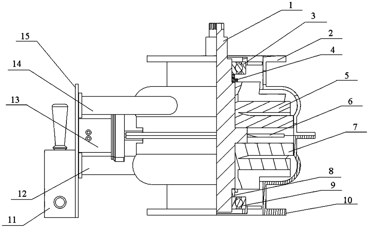
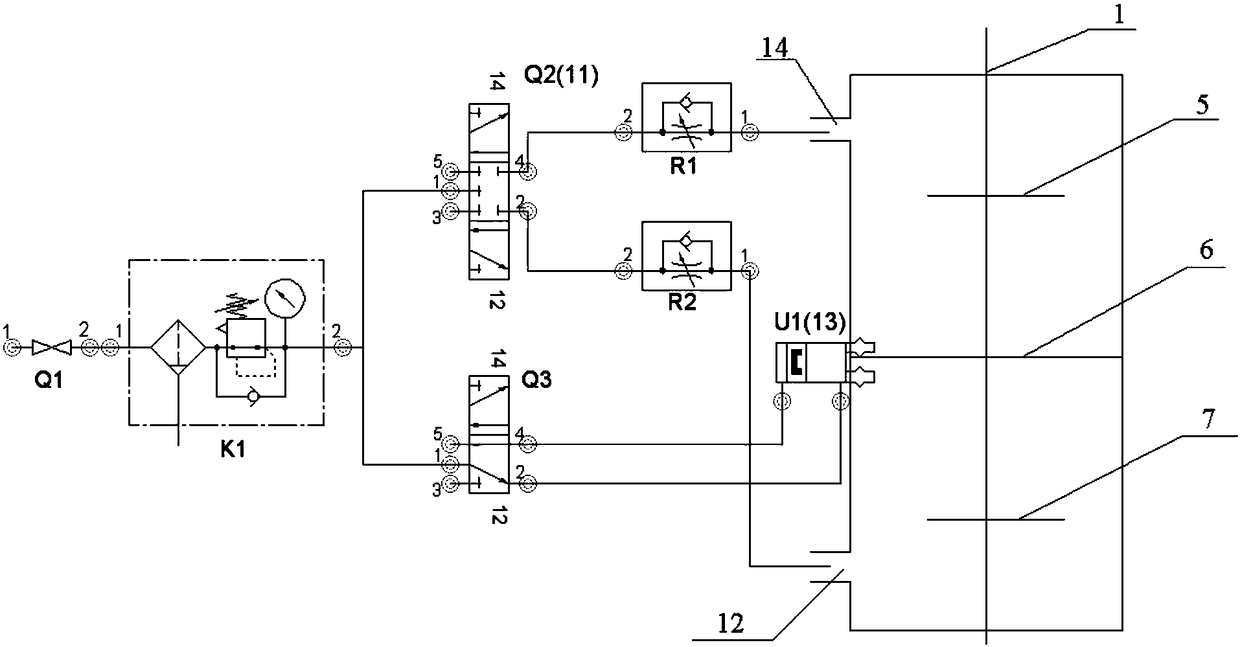
[0024] Such as Figure 1-2 As shown, a gas power device for a parts cleaning machine includes an upper air guide shell 2 and a lower air guide shell 10 with the same structure and relatively connected; the upper air guide shell 2 and the lower air guide shell 10 constitute the device housing; The rotating shaft 1 is arranged in the device housing, and the upper end protrudes from the upper end of the upper wind guide shell 2 to connect to the parts cleaning machine; it also includes an upper impeller 5 and a lower impeller 7 arranged on the rotating shaft 10 with opposite installation directions; the upper impeller 5 is arranged on the upper In the air guide shell 2, the lower impeller 7 is arranged in the lower air guide shell 10; the upper air guide shell 2 is connected to the upper air inlet 14, and the lower air guide shell 10 is connected ...


PUM


Abstract

The invention discloses a gas power device for a part cleaning machine. The gas power device comprises an upper air guide shell and a lower air guide shell which are the same in structure and are oppositely connected; the upper air guide shell and the lower air guide shell form a device shell; a rotating shaft is arranged in the device shell, and the upper end of the rotating shaft extends out ofthe top end of the upper air guide shell and is connected with the part cleaning machine; the gas power device further comprises an upper impeller and a lower impeller, wherein the upper impeller andthe lower impeller are arranged on the rotating shaft and are opposite in installation direction; the upper impeller is arranged in the upper air guide shell, and the lower impeller is arranged in thelower air guide shell; the upper air guide shell communicates with an upper air inlet, and the lower air guide shell communicates with a lower air inlet; a brake device is further arranged on the rotating shaft; and the gas power device also comprises a control unit used for controlling the air flow of the upper air inlet and the lower air inlet, and the control unit is further connected with a brake device. The gas power device is safe, reliable, short in transmission distance, high in efficiency, small in size, and high in integration degree.

Description

technical field [0001] The invention relates to a gas power device, in particular to a gas power device used in a parts washing machine. Background technique [0002] Existing parts cleaning machines generally use motors as the power source for their rotation, flipping, and translation; since the cleaning fluid can conduct electricity, the working voltage of the motor is generally high voltage, and the rotation, flipping, and translation of the cleaning machine during operation, resulting in cleaning Liquid splashing; there is a potential safety hazard of motor water ingress, which endangers the safety of equipment and personnel; the existing parts cleaning machines mostly use sealing of the cleaning box, reasonable arrangement of the inlet and outlet, and the use of sealing rings at the joints of the rotating shaft and the housing. Install the motor in a sealed box, or install the motor far away from the cleaning solution to prevent water from entering the motor and protect...

Claims


Application Information

Patent Timeline
Patent Type & Authority Applications(China)
IPC IPC(8): B08B13/00B08B3/00
CPCB08B13/00B08B3/00
Inventor 杨燕红郑清刘全廖兴华李嘉航张戈陈杨振陈武东刘峰黄艳峰王珊陈镭伍志翔周健雄
Owner XIHUA UNIV
Why Eureka
Try Eureka