
Coating tank convenient to transport
A paint tank and main body technology is applied in the field of paint tanks that are easy to transport, which can solve the problems of inconvenient transportation and high quality, and achieve the effects of time-saving transportation, high support capacity, and reduced resistance.
- Summary
- Abstract
- Description
- Claims
- Application Information
AI Technical Summary
Problems solved by technology
Method used
Image

Examples
Embodiment Construction
[0020] In order to better understand the present invention, the present invention will be further described below in conjunction with specific embodiments and accompanying drawings.
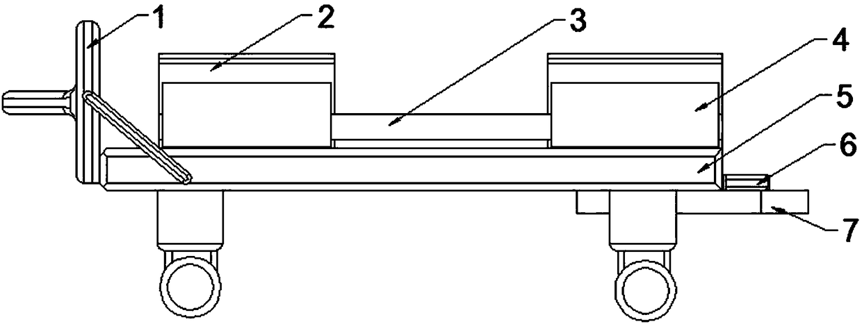
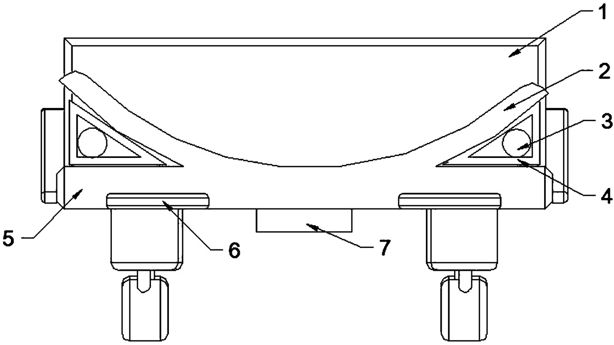
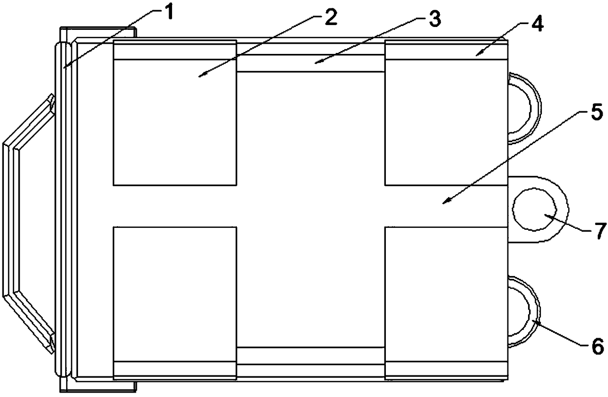
[0021] Such as Figure 1-3 As shown, a paint tank body that is convenient for transportation includes a device main body 5, and the upper end surface of the device body 5 is fixedly provided with a limit block 2 for limiting the position of the tank body, and the limit block 2 and the The second reinforcing body 4 is fixedly connected between the device main bodies 5 , and the first reinforcing body 3 is fixedly connected inside the second reinforcing body 4 . The side of the device main body 5 is provided with a mounting block 7 for connecting the power device, and the mounting block 7 is provided with mounting holes, and the device main body 5 on both sides of the mounting block 7 is also fixedly connected with Auxiliary connection ring body 6 of power unit. A baffle 1 is pivotally connected ...
PUM
 Abstract
Description
Claims
Application Information