
Unmanned aerial vehicle speed estimation method

A speed estimation, UAV technology, applied in computing, navigation calculation tools, image data processing and other directions, can solve problems such as large inaccuracy of UAV speed error, large delay, etc., to reduce data noise and improve data. The effect of precision

Inactive Publication Date: 2018-06-26
HIWING TECH ACAD OF CASIC
View PDF3 Cites 10 Cited by
  • Summary
  • Abstract
  • Description
  • Claims
  • Application Information

AI Technical Summary

Problems solved by technology

[0003] The purpose of the present invention is to overcome the deficiencies of the prior art and provide a method for estimating the speed of a UAV, which can solve the problems of large inaccuracy and large delay in measuring the speed of a UAV based on the principle of optical flow

Method used


Image

  • Unmanned aerial vehicle speed estimation method
  • Unmanned aerial vehicle speed estimation method
  • Unmanned aerial vehicle speed estimation method

Examples


Embodiment Construction

[0026] Specific embodiments of the present invention will be described in detail below in conjunction with the accompanying drawings. In the following description, for purposes of explanation and not limitation, specific details are set forth in order to provide a thorough understanding of the invention. It will be apparent, however, to one skilled in the art that the present invention may be practiced in other embodiments that depart from these specific details.

[0027] It should be noted here that, in order to avoid obscuring the present invention due to unnecessary details, only the device structure and / or processing steps closely related to the solution according to the present invention are shown in the drawings, and the steps related to the present invention are omitted. Invent other details that don't really matter.

[0028] In order to improve the speed measurement accuracy while ensuring real-time measurement, the embodiment of the present invention provides a metho...


PUM


Abstract

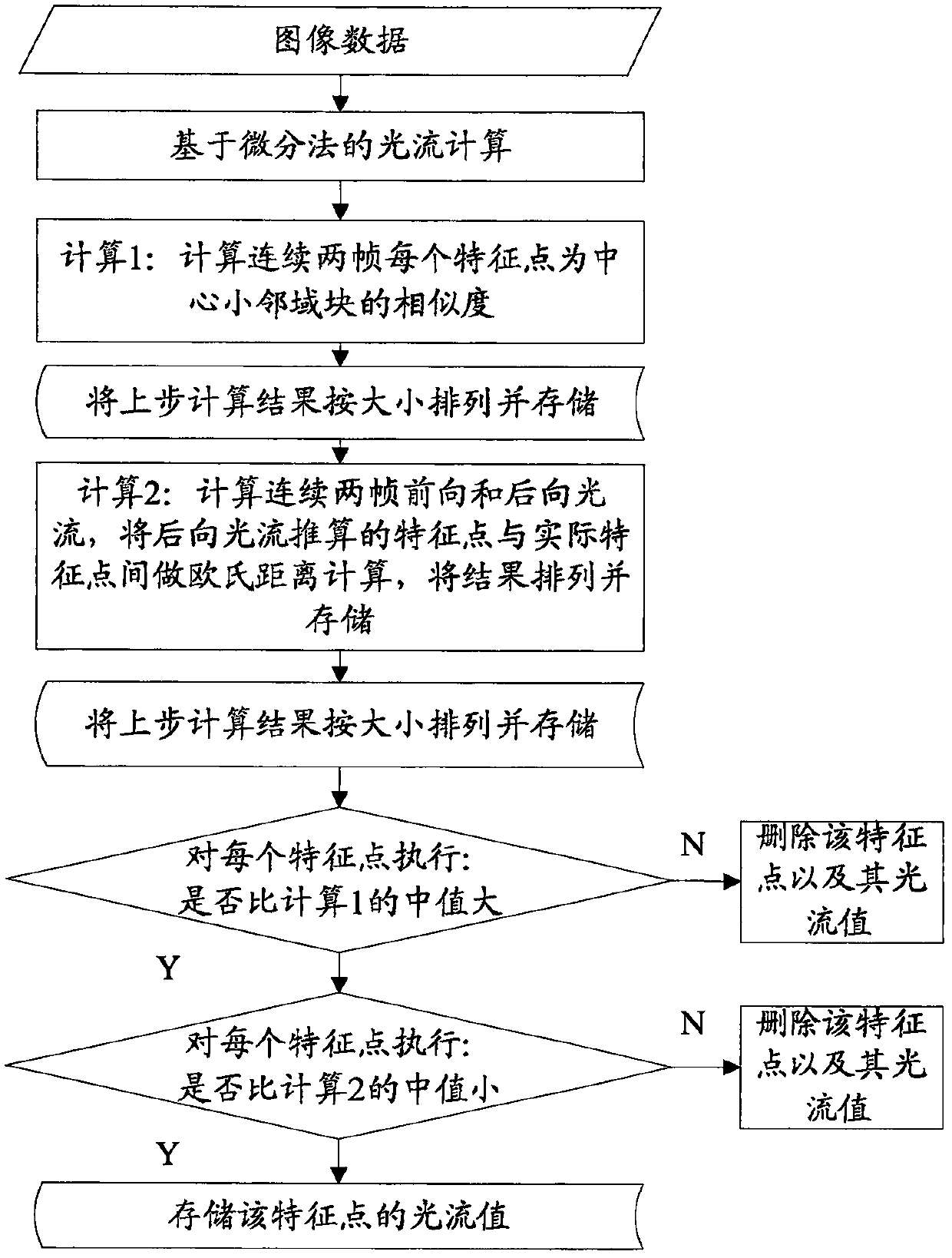
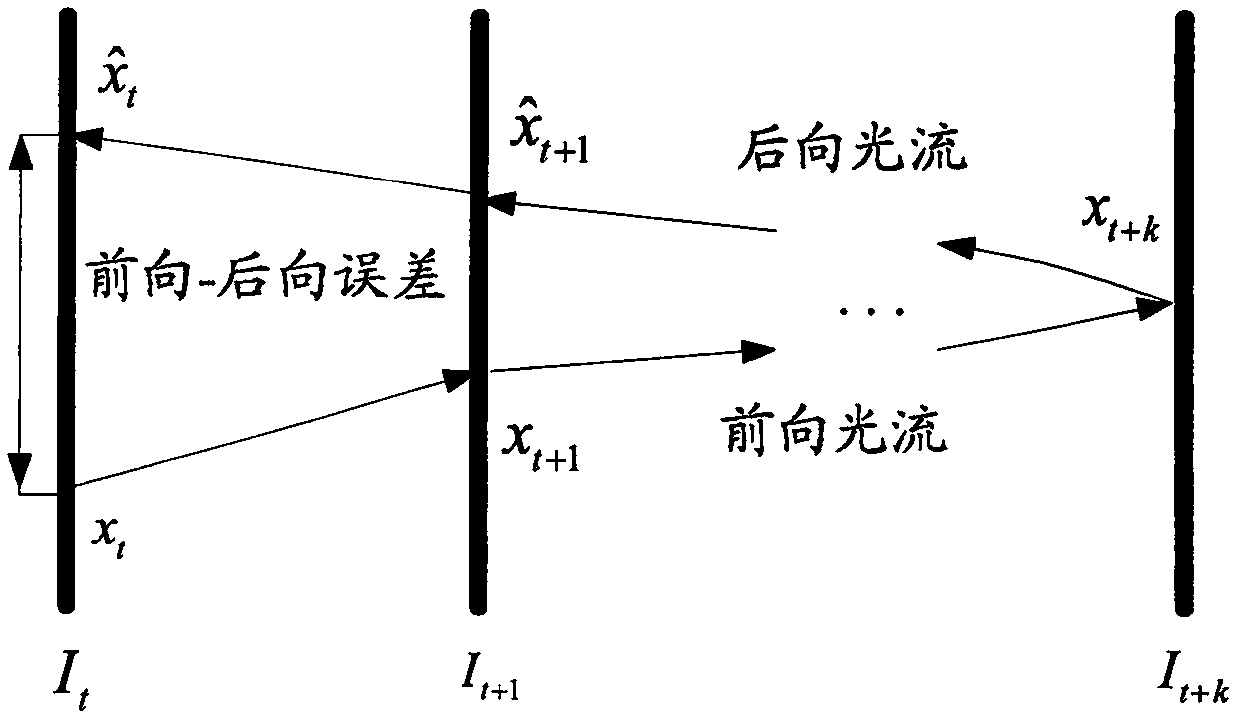
The embodiments of the present invention disclose an unmanned aerial vehicle speed estimation method, and relate to unmanned aerial vehicle navigation and information measurement. A purpose of the present invention is to solve the problems of inaccuracy and high delaying in the measurement of the unmanned aerial vehicle speed through optical flow principle. The unmanned aerial vehicle speed estimation method comprises: calculating the median of the similarity of sparse optical flow feature points, and filtering out the feature point pair with the standard cross-correlation value of less than the median in the feature point set to obtain first sparse optical flow field data; calculating the FB error median of each feature point pair set in the first sparse optical flow field, filtering outthe feature point pair with the FB error of greater than the median to obtain second sparse optical flow field data, and calculating the optical flow value capable of characterizing the actual motionof the unmanned aerial vehicle; and estimating the motion speed by combining the image optical flow value, the camera angular motion and the camera height information. The unmanned aerial vehicle speed estimation method of the present invention is mainly used for estimating the speed of the unmanned aerial vehicle.

Description

technical field [0001] The invention relates to the technical field of unmanned aerial vehicle navigation and information measurement, in particular to a method for estimating the speed of an unmanned aerial vehicle. Background technique [0002] Velocity is a fast variable, and its accuracy requirements are generally high. Using optical flow to measure the ground velocity of UAVs is a kind of UAV navigation application technology. Traditional velocity measurement algorithms based on optical flow often do not consider Start to eliminate the error, the direct measurement value of the speed obtained has a large error, and then use filtering algorithms such as Kalman filtering to smooth the data, which will cause a delay in the data in units of cycles and reduce the real-time performance of the navigation data. Contents of the invention [0003] The purpose of the present invention is to overcome the deficiencies of the prior art and provide a method for estimating the speed ...

Claims


Application Information

Patent Timeline
Patent Type & Authority Applications(China)
IPC IPC(8): G01C21/20G06T7/246
CPCG01C21/20G06T2207/10016G06T2207/20032
Inventor 吴琦刘长林王英勋蔡志浩
Owner HIWING TECH ACAD OF CASIC
Learn More