Valve handle paint-spraying device

A technology of handwheel and valve, applied in the direction of spraying device, spray booth, etc., can solve the problem of painting dead angle and so on

Inactive Publication Date: 2018-06-29
CHONGQING QIANYAN MACHINERY CO LTD
View PDF0 Cites 3 Cited by
  • Summary
  • Abstract
  • Description
  • Claims
  • Application Information

AI Technical Summary

Problems solved by technology

[0004] The present invention intends to provide a valve handwheel paint spraying device to solve the problem that when the traditional paint spraying device paints the valve handwheel, it is easy to produce painting dead ends

Method used


Image

  • Valve handle paint-spraying device
  • Valve handle paint-spraying device

Examples


Embodiment Construction

[0018] The present invention will be described in further detail below by means of specific embodiments:

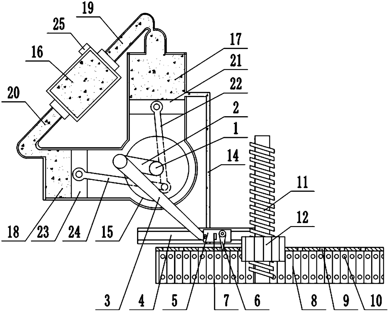
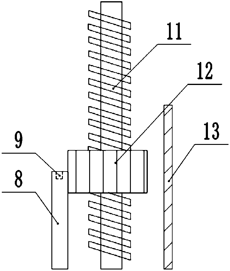
[0019] The reference signs in the drawings of the description include: drive shaft 1, first drive rod 2, second drive rod 3, chute 4, slider 5, drive tooth 6, limit block 7, paint rack 8, card slot 9. Paint spray port 10, screw rod 11, valve hand wheel 12, electric heating plate 13, discharge pipe 14, drive plate 15, material storage box 16, first cylinder 17, second cylinder 18, first material pipe 19 , The second material pipe 20, the first slide plate 21, the first piston rod 22, the second slide plate 23, the second piston rod 24, and the feeding port 25.

[0020] The embodiment is basically as figure 1 , figure 2 Shown: a valve handwheel painting device, including a frame and a driving mechanism, the driving mechanism includes a drive shaft 1 rotatably connected to the frame, the drive shaft 1 is connected to a motor, and the drive shaft 1 is fixedly connected to ...


PUM


Abstract

The invention relates to a valve handle paint-spraying device. The device comprises a rack drive shaft. The drive shaft is fixedly connected with a first drive rod. The other end of the first drive rod is rotationally connected with a second drive rod. The position, below the drive shaft, in a rack is fixedly connected with a slide groove. A slide block is in sliding connection with the interior of the slide groove. The end, away from the first drive rod, of the second drive rod is rotationally connected to the slide block. The slide block is rotationally connected with a drive tooth. One sideof the drive tooth is fixedly connected with a limiting block. A paint-spraying rack is arranged below the slide groove and provided with clamping grooves, paint-spraying outlets and a storage groove. The rack is fixedly connected with a lead screw. An electric heating plate is arranged at one side of the paint-spraying rack. The drive shaft is further connected with an intermittent supply mechanism. The intermittent supply mechanism is provided with a discharging outlet connected with a discharging pipe. The other end of the discharging pipe is connected with the storage groove of the paint-spraying rack. Through the device, the problem that during paint-spraying of a valve handle, paint-spraying dead angles are prone to emerging is solved.

Description

technical field [0001] The invention relates to the field of painting devices, in particular to a valve handwheel painting device. Background technique [0002] A valve is a device used to control the direction, pressure, and flow of a fluid in a fluid system. A valve is a device that makes or stops the flow of media (liquid, gas, powder) in piping and equipment and controls its flow. Valves can be used to control the flow of various types of fluids such as air, water, steam, various corrosive media, mud, oil, liquid metal and radioactive media. The valve is a control component in the pipeline fluid delivery system. It is used to change the passage section and the flow direction of the medium, and has the functions of diversion, cut-off, throttling, check, diversion or overflow relief. [0003] The realization of the above-mentioned valve functions is usually achieved by turning the valve handwheel. According to different shapes, the valve handwheel can be divided into dis...

Claims


Application Information

Patent Timeline
Patent Type & Authority Applications(China)
IPC IPC(8): B05B16/20B05B13/04B05B13/02B05B15/20
CPCB05B13/041B05B13/0235
Inventor 罗贵良
Owner CHONGQING QIANYAN MACHINERY CO LTD
Why Eureka
Try Eureka