Sieve for automatic discharge

An automatic feeding and sieving technology, applied in the field of sieves, can solve the problems of low efficiency, small amount of one-time screening, and large time consumption

Active Publication Date: 2018-06-29
JIANGSU YUBO AUTOMATION EQUIP CO LTD
View PDF5 Cites 2 Cited by
  • Summary
  • Abstract
  • Description
  • Claims
  • Application Information

AI Technical Summary

Problems solved by technology

[0004] In order to overcome the need for manpower to shake in the process of sifting things, the present invention takes a lot of time and is inefficient. In the process of shaking, the strength of artificial shaking is not enough, and the amount of one-time screening is small, especially in large-scale screening. When it is necessary to consume a lot of manpower and time and has the disadvantages of low efficiency, the technical problem to be solved by the present invention is to provide a machine to replace the sieve for manual automatic feeding

Method used


Image

  • Sieve for automatic discharge
  • Sieve for automatic discharge
  • Sieve for automatic discharge

Examples


Embodiment 1

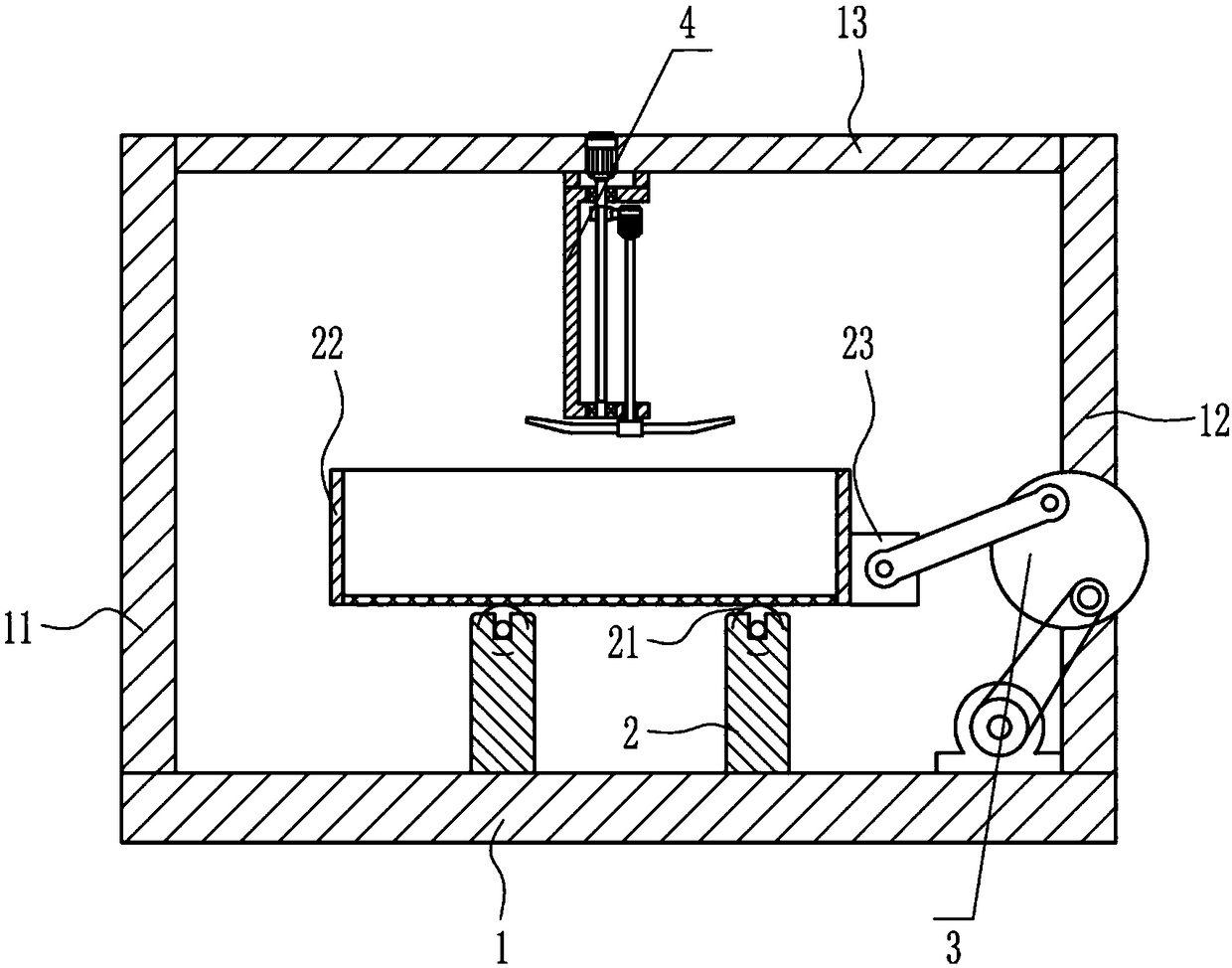
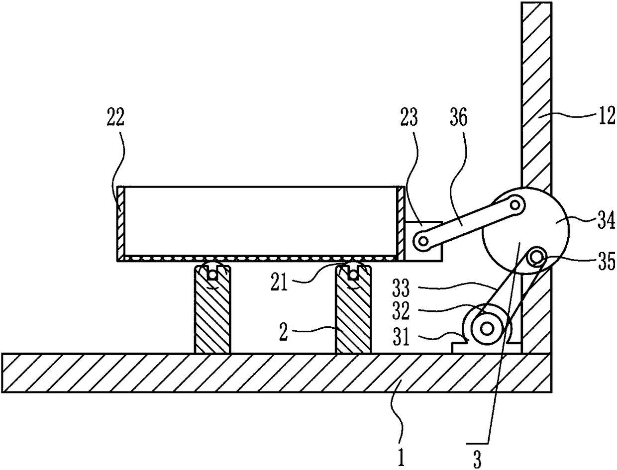
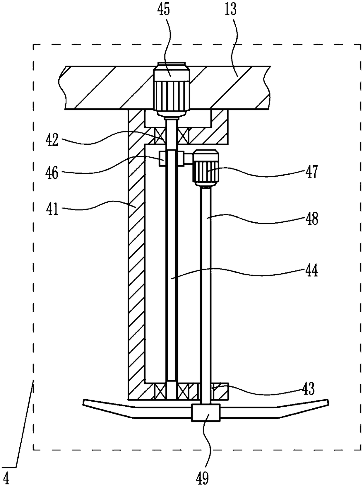
[0033] A sieve for automatic feeding, such as Figure 1-8 As shown, it includes a base 1, a first support 11, a second support 12, a third support 13, a first support plate 2, idler rollers 21, a screen frame 22, a mounting block 23, a transmission device 3 and a stirring device 4. The left side above the base 1 is fixedly connected with a first support 11, the right side above the base 1 is fixedly installed with a second support 12, the upper right side of the first support 11 is fixedly installed with a third support 13, and the upper left side of the second support 12 Connected with the other end of the third support 13, the first support plate 2 is symmetrically installed on the top of the base 1, and the idler roller 21 is rotatably installed on the first support plate 2, and the screen frame 22 is arranged above the idler roller 21. Frame 22 is contact-connected with idler roller 21, and installation block 23 is fixedly installed under the outer side of the right wall o...

Embodiment 2

[0035] A sieve for automatic feeding, such as Figure 1-8 As shown, it includes a base 1, a first support 11, a second support 12, a third support 13, a first support plate 2, idler rollers 21, a screen frame 22, a mounting block 23, a transmission device 3 and a stirring device 4. The left side above the base 1 is fixedly connected with a first support 11, the right side above the base 1 is fixedly installed with a second support 12, the upper right side of the first support 11 is fixedly installed with a third support 13, and the upper left side of the second support 12 Connected with the other end of the third support 13, the first support plate 2 is symmetrically installed on the top of the base 1, and the idler roller 21 is rotatably installed on the first support plate 2, and the screen frame 22 is arranged above the idler roller 21. Frame 22 is contact-connected with idler roller 21, and installation block 23 is fixedly installed under the outer side of the right wall o...

Embodiment 3

[0038] A sieve for automatic feeding, such as Figure 1-8 As shown, it includes a base 1, a first support 11, a second support 12, a third support 13, a first support plate 2, idler rollers 21, a screen frame 22, a mounting block 23, a transmission device 3 and a stirring device 4. The left side above the base 1 is fixedly connected with a first support 11, the right side above the base 1 is fixedly installed with a second support 12, the upper right side of the first support 11 is fixedly installed with a third support 13, and the upper left side of the second support 12 Connected with the other end of the third support 13, the first support plate 2 is symmetrically installed on the top of the base 1, and the idler roller 21 is rotatably installed on the first support plate 2, and the screen frame 22 is arranged above the idler roller 21. Frame 22 is contact-connected with idler roller 21, and installation block 23 is fixedly installed under the outer side of the right wall o...


PUM


Abstract

The invention relates to a sieve, in particular to a sieve for automatic discharge. The technical purpose of providing the sieve replacing manpower with machinery for automatic discharge is achieved.In order to achieve the technical purpose, the sieve for automatic discharge comprises a base, a first support, a second support, a third support, first support plates, carrier rollers and the like; the first support is fixedly connected to the left side of the upper portion of the base, the second support is fixedly installed on the right side of the upper portion of the base, the third support is fixedly installed on the upper portion of the right side of the first support, the upper portion of the left side of the second support is connected with the other end of the third support, the first support plates are symmetrically installed on the left and the right of the top of the base, and the carrier rollers are rotationally installed on the first support plates. Equipment specially for the sieve for automatic discharge is developed, the function of automatic discharge screening is achieved, shaking is performed uniformly, manpower is saved, the efficiency is high, and in the machineworking process, manpower and material resources are greatly saved.

Description

technical field [0001] The invention relates to a sieve, in particular to a sieve for automatic feeding. Background technique [0002] Generally, in the process of sieving things, manpower is required to shake. Manual shaking takes a lot of time, and the efficiency is low. In the process of shaking, the strength of manual shaking is not enough, and the amount of one-time screening is small. It consumes a lot of manpower and time and is inefficient, so there is an urgent need for a machine to replace the sieve for manual automatic feeding. Contents of the invention [0003] (1) Technical problems to be solved [0004] In order to overcome the need for manpower to shake in the process of sifting things, the present invention needs a lot of time for manual shaking, and the efficiency is low. When it is used, it needs to consume a lot of manpower and time and has the disadvantages of low efficiency. The technical problem to be solved by the present invention is to provide a ...

Claims


Application Information

Patent Timeline
Patent Type & Authority Applications(China)
IPC IPC(8): B07B1/30B07B1/42B07B1/46
CPCB07B1/30B07B1/42B07B1/46
Inventor 鲁校斌陈蕴博黄丰
Owner JIANGSU YUBO AUTOMATION EQUIP CO LTD
Why Eureka
Try Eureka