Punching equipment

A technology of punching and equipment, applied in the field of mechanical processing, can solve the problems of slow punching speed, complicated operation, expensive price, etc., and achieve the effect of increasing efficiency and high hole precision

Inactive Publication Date: 2018-06-29
徐萍
View PDF7 Cites 0 Cited by
  • Summary
  • Abstract
  • Description
  • Claims
  • Application Information

AI Technical Summary

Problems solved by technology

[0002] In the process of mechanical processing and manufacturing, it is necessary to punch the plate to facilitate the fixed installation of other parts on the plate. The traditional punching method is manually operated by the worker, the punching speed is slow, it takes a long time, and the punching position is easy to miss. It causes a waste of plates and cannot meet the production needs. The automatic punching equipment currently on the market is complicated to operate and expensive, and cannot be widely promoted.

Method used


Image

  • Punching equipment
  • Punching equipment
  • Punching equipment

Examples


Embodiment Construction

[0020] The preferred embodiments of the present invention will be described in detail below in conjunction with the accompanying drawings, so that the advantages and features of the present invention can be more easily understood by those skilled in the art, so as to define the protection scope of the present invention more clearly.

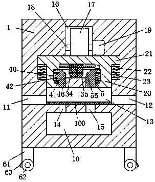
[0021] refer to Figure 1-6The shown punching equipment includes a body 1, the bottom of the body 1 is fixedly provided with feet 61 around, the bottom of the feet 61 is fixedly provided with moving rollers 62, and the outside of the bottom of the feet 61 is fixedly provided with The braking brake 63 of the moving roller 62, the body 1 is provided with a first sliding groove 13 and a receiving groove 10, and a first communication channel is provided between the first sliding groove 13 and the receiving groove 10. Groove 14 and second through groove 15, described first through groove 14 is positioned at the left side of described second through gr...


PUM


Abstract

The invention discloses punching equipment. The punching equipment comprises a machine body. Supporting legs are fixedly arranged on the periphery of the bottom face of the machine body. Movable rolling wheels are fixedly arranged at the bottoms of the supporting legs. Damper brakes used for fixing the movable rolling wheels are fixedly arranged at the outer sides of the bottoms of the supportinglegs. A first slippage groove and a containing groove are formed in the machine body. A first through groove and a second through groove are formed between the first slippage groove and the containinggroove in a connecting mode. The first through groove is located in the left side of the second through groove. An exiting groove and an entering groove connected with the outside of the machine bodyare equally formed in the left end and the right end of the bottom of the first slippage groove. A punching slippage block capable of sliding up and down is formed in the first slippage groove. Firstcontaining grooves are equally formed in the left end wall and the right end wall of the first slippage groove. The punching equipment is simple in overall structure, safe and reasonable in design and low in manufacturing and production cost. The punching equipment is accurate in punching machining precision, high in stability and capable of decreasing defective goods produced in the board punching process.

Description

technical field [0001] The invention relates to the field of mechanical processing, in particular to a punching device. Background technique [0002] In the process of mechanical processing and manufacturing, it is necessary to punch the plate to facilitate the fixed installation of other parts on the plate. The traditional punching method is manually operated by the worker, the punching speed is slow, it takes a long time, and the punching position is easy to miss. It causes waste of plates and cannot adapt to production needs. The automatic punching equipment currently on the market is complicated to operate, expensive, and cannot be widely promoted. Contents of the invention [0003] The technical problem to be solved by the present invention is to provide a punching device, which can solve the above-mentioned problems in the prior art. [0004] In order to solve the above problems, the present invention adopts the following technical solution: a punching equipment of ...

Claims


Application Information

Patent Timeline
Patent Type & Authority Applications(China)
IPC IPC(8): B21D28/26B21D28/34B21D43/00B21D45/04B21D37/04
CPCB21D28/26B21D28/34B21D37/04B21D43/003B21D45/003B21D45/04
Inventor 徐萍
Owner 徐萍
Why Eureka
Try Eureka