

Gear chamfering and deburring composite device
A composite device and deburring technology, applied in the direction of belts/chains/gears, gear teeth, components with teeth, etc., can solve the problem of affecting the axial size and end surface roughness of parts, the end surface burrs of parts cannot be completely removed, and the increase of equipment , management and labor costs, etc., to achieve the effect of high cost performance, simple structure, and reduced cleaning intensity
Inactive Publication Date: 2018-06-29
CHONGQING SHUNHUAI MACHINERY MFG CO LTD
View PDF8 Cites 3 Cited by
- Summary
- Abstract
- Description
- Claims
- Application Information
AI Technical Summary
Problems solved by technology
The use of this chamfering machine for chamfering of gear parts has the following disadvantages: firstly, chamfering adopts a separate process, which increases the cost of equipment, management and labor; The end surface burr cannot be completely removed, which affects the axial dimension and end surface roughness of the part, and requires subsequent finishing
Method used
View moreImage
Smart ImageViewing Examples

Examples
Embodiment Construction
[0013] The present invention will be described in further detail below by means of specific embodiments:
Login to View More PUM
 Abstract
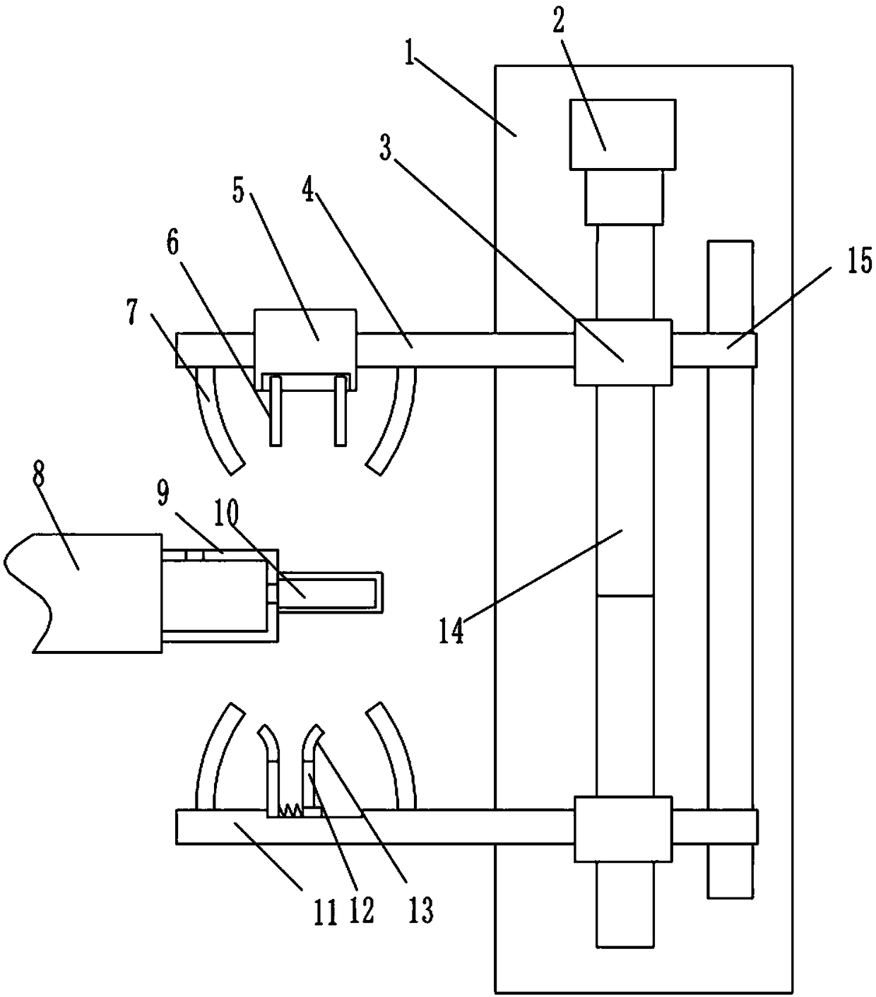
The invention belongs to the technical field of gear machining equipment, and particularly discloses a gear chamfering and deburring composite device. The gear chamfering and deburring composite device comprises a rack and a workbench. The rack is provided with a drive motor. The drive motor is connected with a fixing shaft for gear fixing and an air expansion shaft. The workbench is provided witha servo motor. The servo motor is connected with a both-way lead screw provided with two nut supports. The two nut supports are connected with a first movable rod and a second movable rod correspondingly. The first movable rod is provided with two burr cutters, and the second movable rod is provided with two burr cutters. A spring is connected between the two burr cutters. The right burr cutter is in sliding connection to the second movable rod. Arc sheets are arranged at the end portions of the burr cutters, and the end portions of the arc sheets are bent towards the outer side. Protection covers are arranged on the two sides of the two chamfering cutters and the two sides of the two burr cutters and are bent towards the close side, and a scrap collection box is arranged at the lower endof each protection cover. According to the scheme, gear end face deburring treatment can be finished while gear chamfering treatment is achieved.
Description
technical field [0001] The invention belongs to the technical field of gear processing equipment, and in particular relates to a gear chamfering and deburring compound device. Background technique [0002] The gear hobbing process generally includes multiple processes such as rough rolling → chamfering → deburring → fine rolling. Since the existing gear hobbing machines cannot complete the chamfering and deburring processes, the existing gear hobbing production line needs to include at least two gear hobbing machines and one chamfering machine. The chamfering machine is located between the two gear hobbing machines, and one of the gear hobbing machines One is used for rough hobbing of gear workpieces and another gear hobbing machine is used for finish hobbing of gear workpieces. After the rough rolling and fine rolling, the gear needs to be chamfered by a chamfering machine. After the chamfering is completed, it is deburred manually or mechanically. [0003] At present, fo...
Claims
Login to View More Application Information
Patent Timeline
 Patent Type & AuthorityApplications(China)
IPC IPC(8): B23F19/00B23F19/10B23Q11/00B23Q11/08
CPCB23F19/104B23F19/00B23Q11/0042B23Q11/08
Inventor刘险峰
OwnerCHONGQING SHUNHUAI MACHINERY MFG CO LTD