
A mems microstructure four-axis vibration device with piezoelectric ceramics as the excitation source
A piezoelectric ceramic and vibration excitation device technology, applied in the field of MEMS microstructure four-axis vibration excitation device, can solve the problems of large parallelism error, inflexibility, increase in measurement result error, etc., and achieve accurate preload force data. , The adjustment process is smooth, and the effect of reducing the shear force
- Summary
- Abstract
- Description
- Claims
- Application Information
AI Technical Summary
Problems solved by technology
Method used
Image

Examples
Embodiment Construction
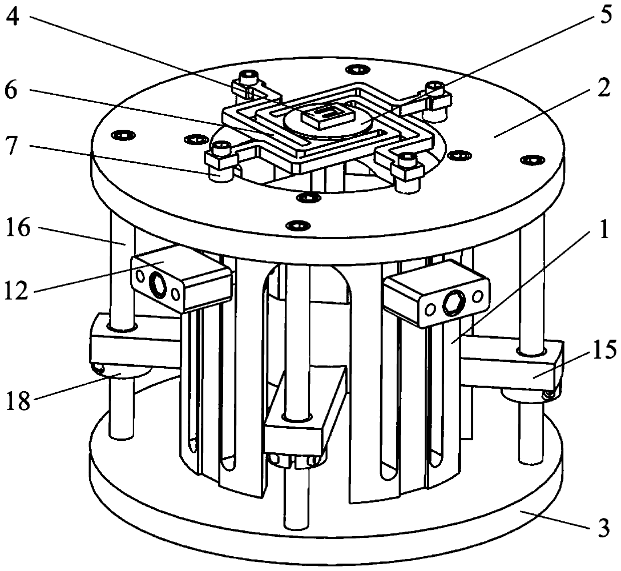
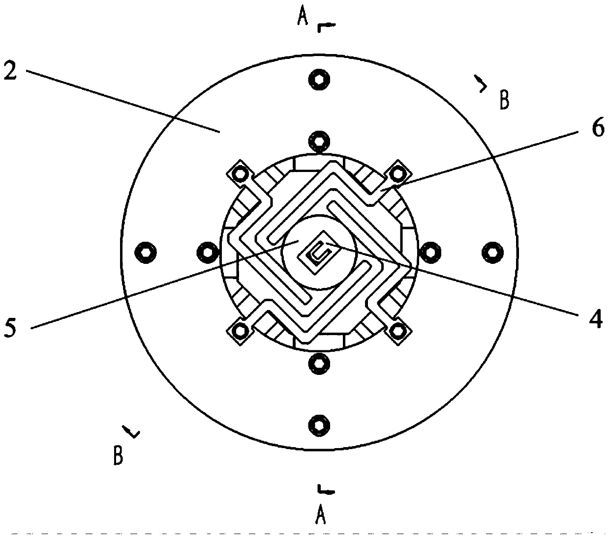
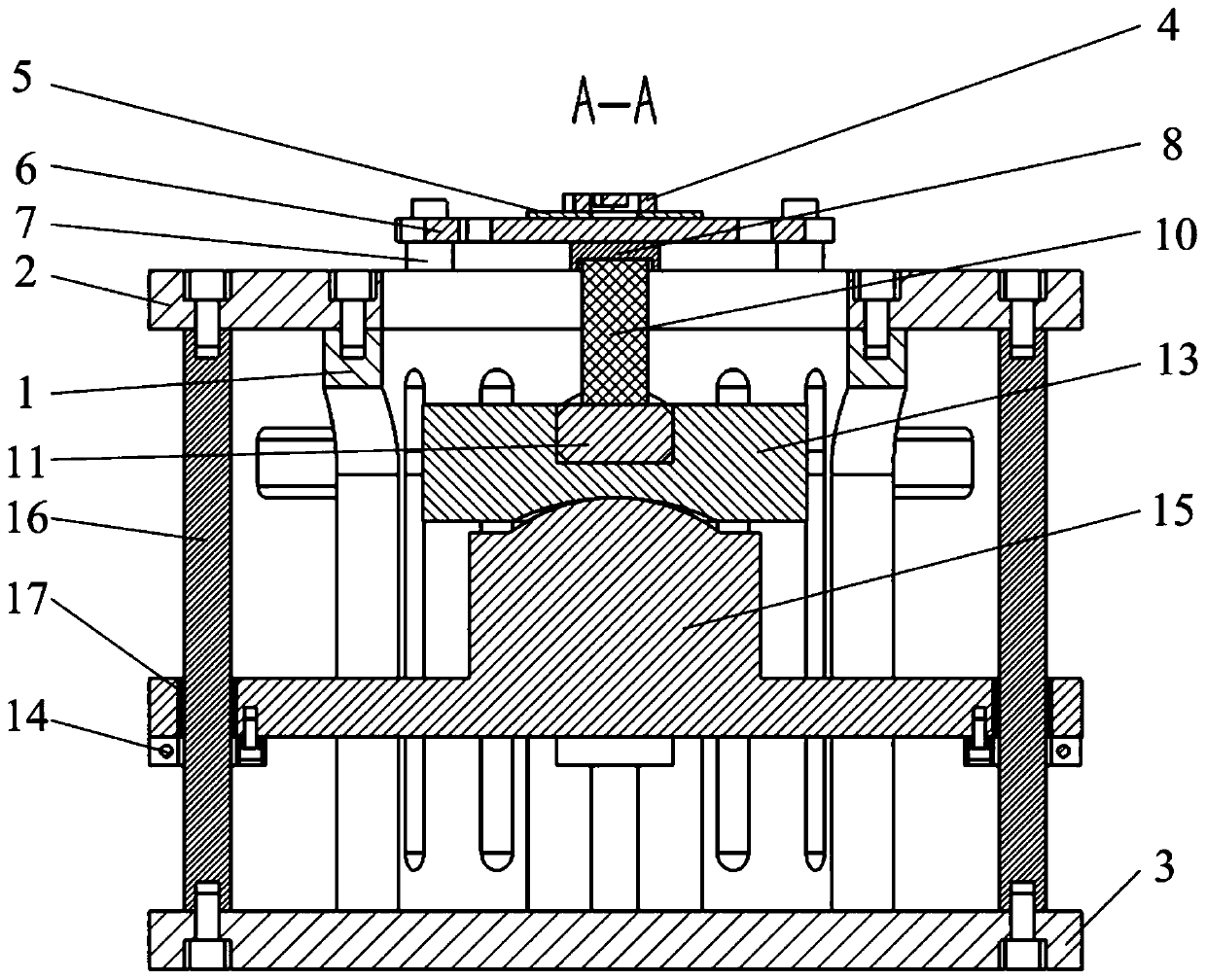
[0041] Such as Figure 1 to Figure 8 As shown, the present invention relates to a MEMS microstructure four-axis vibration device using piezoelectric ceramics as an excitation source, including a hollow sleeve 1, and stacked piezoelectric ceramics 10, a pressure sensor and a pressure sensor are arranged in the sleeve 1. 11 and a movable base composed of an upper coupling block 13 and a lower coupling block 15, an elastic support 6 and a MEMS microstructure 4 are arranged on the sleeve 1.
[0042] An annular top plate 2 and a bottom plate 3 with equal outer diameters and larger than the outer diameter of the sleeve are respectively fixed by screws on the top and bottom of the sleeve 1 , and the MEMS microstructure 4 is mounted on the annular top plate 2 through elastic supports 6 . The elastic support includes a square base plate 602 and four support arms 601 uniformly distributed around the circumference, each support arm 601 is composed of a first connecting arm 6011, a second...
PUM
 Abstract
Description
Claims
Application Information