

Equipment convenient for mounting bridge support
A bridge support and equipment technology, applied in the field of equipment that facilitates the installation of bridge supports, can solve problems such as deformation of pre-embedded steel bars and difficulties in installing bridge supports, and achieve the effects of improving the use effect, saving procedures, and facilitating the installation process
- Summary
- Abstract
- Description
- Claims
- Application Information
AI Technical Summary
Problems solved by technology
Method used
Image

Examples
Embodiment 1
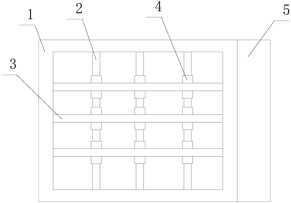
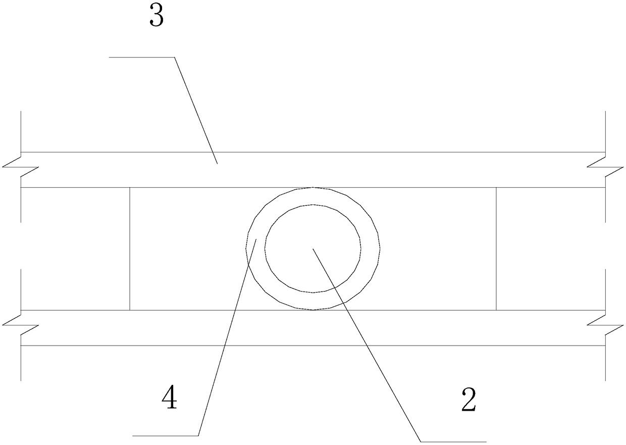
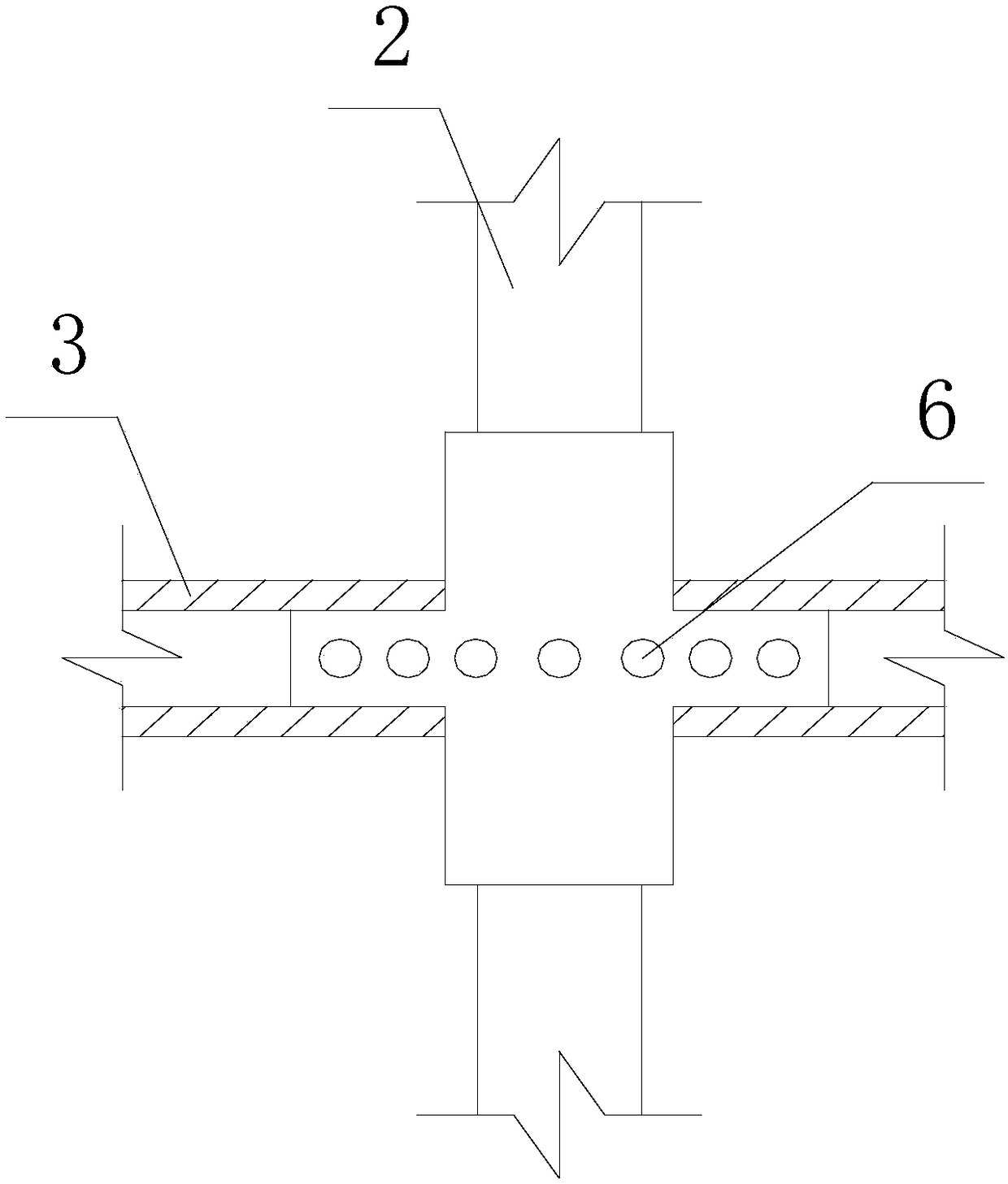
[0039] Such as figure 1 , figure 2 and image 3 As shown, the present invention facilitates the installation of bridge supports, including a frame 1, a longitudinal clamp bar 2, a transverse clamp bar 3 and a sleeve 4; the longitudinal clamp bar 2 and the transverse clamp bar 3 are movably arranged inside the frame 1, and The angle between the longitudinal clamping bar 2 and the transverse clamping bar 3 is 90°; the intersecting longitudinal clamping bar 2 and the transverse clamping bar 3 are movably connected through the sleeve 4; The cylinder 4 moves longitudinally along the transverse clamp rod 3 in the through hole; the outer surface of the sleeve 4 is provided with a spring ball 6 longitudinally along the transverse clamp rod 3; the longitudinal clamp rod 2 is arranged inside the sleeve 4 and along the The longitudinal clamping rod 2 moves longitudinally; the inner wall of the sleeve 4 is provided with balls longitudinally along the longitudinal clamping rod 2 .
[0...
Embodiment 2
[0043] In this embodiment, on the basis of Embodiment 1, the longitudinal clamping bar 2 and the horizontal clamping bar 3 are movably connected to the frame 1, and the longitudinal clamping bar 2 moves longitudinally along the horizontal clamping bar 3, and the horizontal clamping bar 3 moves along the longitudinal clamping bar 2. longitudinal movement.
[0044] During the implementation of this embodiment, in order to enable the longitudinal clamping bar 2 and the horizontal clamping bar 3 to better complete the clamping of the pre-embedded steel bars, the present invention limits the moving direction of the longitudinal clamping bar 2 and the horizontal clamping bar 3 .
Embodiment 3
[0046] Such as figure 1 As shown, on the basis of Embodiment 1, this embodiment further includes a transmission device 5; the transmission device 5 is connected to the longitudinal clamping rod 2 and the lateral clamping rod 3 through a screw.
[0047] When this embodiment is implemented, the pre-embedded steel tends to bear a relatively large stress. When the longitudinal clamping bar 2 and the horizontal clamping bar 3 are adjusted completely by manpower, it is easy to have a large error. Therefore, the present invention uses the transmission device 5 to amplify the power or Adding external power to the transmission device can effectively improve the use effect of the present invention.
PUM
 Abstract
Description
Claims
Application Information