Practical mining device
A practical, cooperative connection technology, applied in supporting devices, earth-moving drilling, drilling equipment and methods, etc., can solve the problems of low precision, easy drilling crooked by manual drilling, time-consuming and labor-intensive, etc., to improve operation stability, prevent overturned effect
- Summary
- Abstract
- Description
- Claims
- Application Information
AI Technical Summary
Problems solved by technology
Method used
Image

Examples
Embodiment Construction
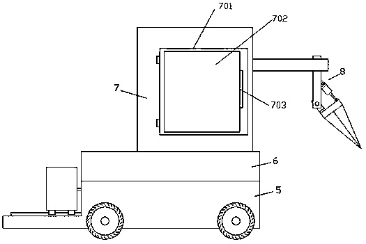
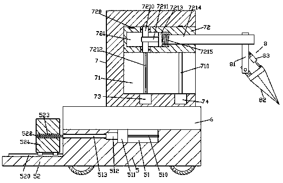
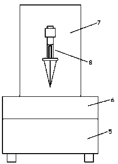
[0016] Such as figure 1 , figure 2 and image 3 As shown, a practical mining device of the present invention includes a base body 5, a sliding frame 6 mounted on the top of the base body 5 with sliding fit, and a lifter 7 fixed on the top of the sliding frame 6. The top surface of the seat body 5 is provided with a first guide groove 51, and the first guide groove 51 is provided with a first screw rod 510 extending left and right, and the left side of the first screw rod 510 is extended. Cooperate with the first electric rotating machine 512, the outer surface of the first electric rotating machine 512 is set in the inner wall on the left side of the first guide groove 51, and the right extension tail of the first screw rod 510 is connected with the first The inner wall on the right side of the guide groove 51 is rotationally fitted and connected, and a first guide block 511 is connected to the first guide groove 51 in a sliding fit and thread fit with the first screw rod 5...
PUM
 Abstract
Description
Claims
Application Information
 - Generate Ideas
- Intellectual Property
- Life Sciences
- Materials
- Tech Scout
- Unparalleled Data Quality
- Higher Quality Content
- 60% Fewer Hallucinations
Browse by: Latest US Patents, China's latest patents, Technical Efficacy Thesaurus, Application Domain, Technology Topic, Popular Technical Reports.
© 2025 PatSnap. All rights reserved.Legal|Privacy policy|Modern Slavery Act Transparency Statement|Sitemap|About US| Contact US: help@patsnap.com