Centrifugal pump system

A technology of centrifugal pump and body, applied in the direction of pump, pump control, pump components, etc., can solve the problem of wasting labor and so on

Inactive Publication Date: 2018-06-29
江苏双轮泵业机械制造有限公司
View PDF7 Cites 0 Cited by
  • Summary
  • Abstract
  • Description
  • Claims
  • Application Information

AI Technical Summary

Problems solved by technology

Therefore, if each centrifugal pump is equipped with a staff member to control it, it will greatly waste labor.

Method used


Image

  • Centrifugal pump system
  • Centrifugal pump system

Examples


Embodiment Construction

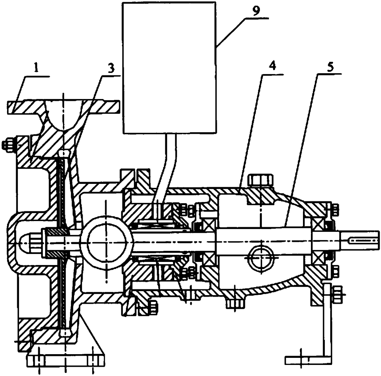
[0006] Please refer to Figure 1-Figure 2 , In an embodiment of the present application, the centrifugal pump system includes: a centrifugal pump, and the centrifugal pump further includes: a body 1; a transmission rod 5, one end of which is arranged inside the body; a bearing 4, arranged on one side of the body The rotating blade 3 is arranged on the transmission rod; the sealing member is arranged at the water inlet of the body; the water storage container 9 is connected to the sealing member.

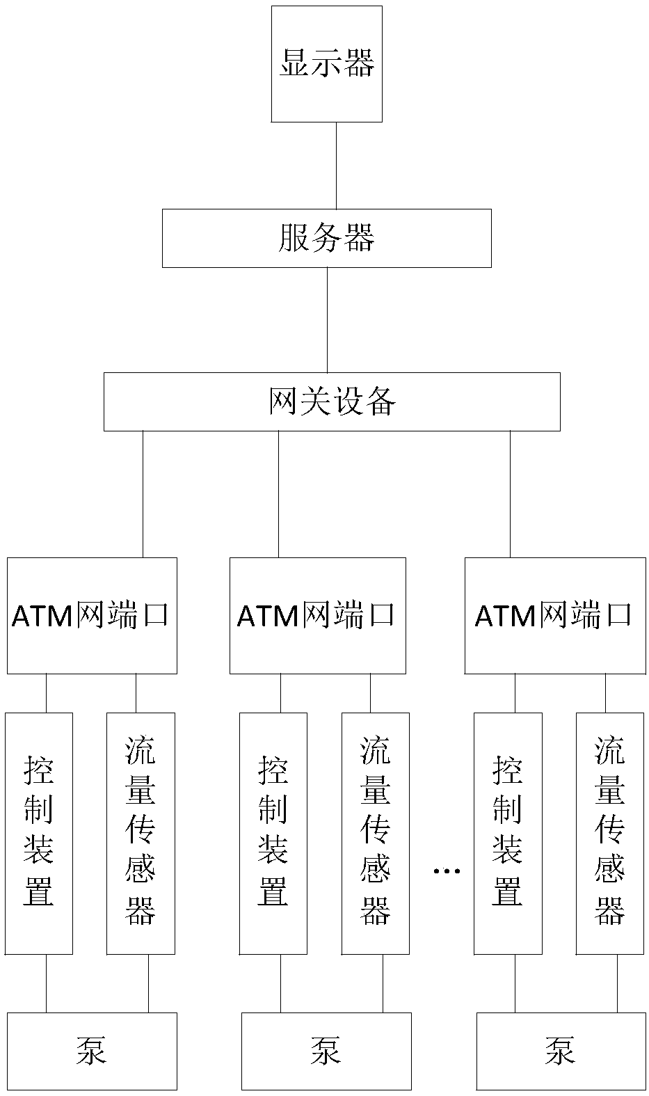
[0007] In an embodiment of the present application, the centrifugal pump system further includes: a flow sensor connected to the centrifugal pump for detecting the flow of the pump; an ATM network port; a gateway device connected to the ATM network port; a server connected to the The gateway device; the display, connected to the server; the control device, connected to the centrifugal pump; the flow sensor transmits the flow signal of the centrifugal pump to the server through the AT...


PUM


Abstract

A centrifugal pump system comprises centrifugal pumps; and each centrifugal pump comprises a centrifugal pump body, a transmission rod of which one end is arranged in the centrifugal pump body, a bearing arranged on one side of the centrifugal pump body, rotary blades arranged on the transmission rod, a sealing part arranged at a water inlet of the centrifugal pump body, a water storage containerconnected with the sealing part, a flow sensor, an ATM network port, a gateway device, a server, a displayer and a control device. According to the centrifugal pump system provided by the invention, the flow rates of the multiple centrifugal pumps are transmitted to the background servers, and the background servers can control the working power of the centrifugal pumps so that the flow rates canbe changed. The purpose that one worker can remotely control all the centrifugal pumps is achieved, and the workers are saved.

Description

technical field [0001] The present invention relates to centrifugal pump systems. Background technique [0002] Centrifugal pumps are used to extract or send liquids under pressure. Generally, the flow of the liquid is controlled manually. However, in large projects, it is generally necessary to use multiple centrifugal pumps for work. Therefore, if each centrifugal pump is equipped with a staff to control, it will greatly waste labor. Contents of the invention [0003] In order to solve the above problems, an embodiment of the present invention provides a centrifugal pump system, including: a centrifugal pump, the centrifugal pump further includes: a body; a transmission rod, one end is arranged inside the body; a bearing is arranged in the One side of the body; the rotating blade is arranged on the transmission rod; the sealing part is arranged at the water inlet of the body; the water storage container is connected to the sealing part; the flow sensor is connected to...

Claims


Application Information

Patent Timeline
IPC IPC(8): F04D15/00F04D29/00
CPCF04D15/00F04D15/0066F04D29/007
Inventor 沈建
Owner 江苏双轮泵业机械制造有限公司
Why Eureka
Try Eureka