
Interference testing system between millimeter wave radar and radio astronomy

A millimeter-wave radar and interference test technology, applied in radio wave measurement systems, instruments, etc., can solve the problems of error-prone calculation results, large amount of calculation, huge manpower and material resources, etc., to avoid weather uncertainty and unknown radio The influence of interference, the guarantee of real reliability, the effect of avoiding large consumption

Active Publication Date: 2018-06-29
THE STATE RADIO MONITORING CENT TESTING CENT
View PDF4 Cites 4 Cited by
  • Summary
  • Abstract
  • Description
  • Claims
  • Application Information

AI Technical Summary

Problems solved by technology

[0009] The current theoretical calculation method mainly has three shortcomings: First, the millimeter-wave radar radio frequency parameters in the theoretical calculation parameters are only the radar setting parameters, but in actual situations, the emission index often deviates from the setting parameters, which will easily cause the final calculation. The deviation of the results; second, the actual environment of the radio astronomy observatory is very complex (including mountains, plains, forests, buildings, weather and climate, etc.), the establishment of mathematical models can only be aimed at the more typical ideal situations, and cannot cover most complex environment; third, theoretical calculations require the use of various models for complex calculations, the analysis is complex and cumbersome, the amount of calculation is large, and the calculation results are prone to errors
[0010] The existing actual field tests mainly have three shortcomings: First, the actual test is carried out without determining the interference between millimeter-wave radar and radio astronomy, which is likely to cause business interference to radio astronomy, which is very dangerous and not allowed Second, the actual environment has a very high noise floor, the environment is harsh, and the signal is prone to attenuation. The test results themselves will be affected by factors such as weather uncertainty and unknown radio interference; third, the actual test generally requires a large number of tests, covering Various environments, which result in a very large workload and require huge manpower and material resources

Method used


Image

  • Interference testing system between millimeter wave radar and radio astronomy
  • Interference testing system between millimeter wave radar and radio astronomy
  • Interference testing system between millimeter wave radar and radio astronomy

Examples


Embodiment Construction

[0031] Hereinafter, exemplary embodiments of the present disclosure will be described in more detail with reference to the accompanying drawings. Although exemplary embodiments of the present disclosure are shown in the drawings, it should be understood that the present disclosure can be implemented in various forms and should not be limited by the embodiments set forth herein. On the contrary, these embodiments are provided to enable a more thorough understanding of the present disclosure and to fully convey the scope of the present disclosure to those skilled in the art.

[0032] According to the World Radio Conference (WRC) resolution, the frequency band that can be used by millimeter-wave radar services is mainly concentrated between 76-81 GHz. According to radio frequency allocation regulations, the main business of this frequency band also includes radio astronomy. According to national laws and WRC resolutions, radio astronomy is a key protected business, and any other bu...


PUM


Abstract

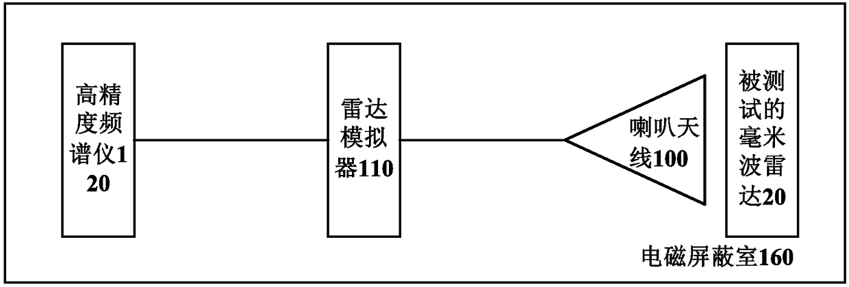
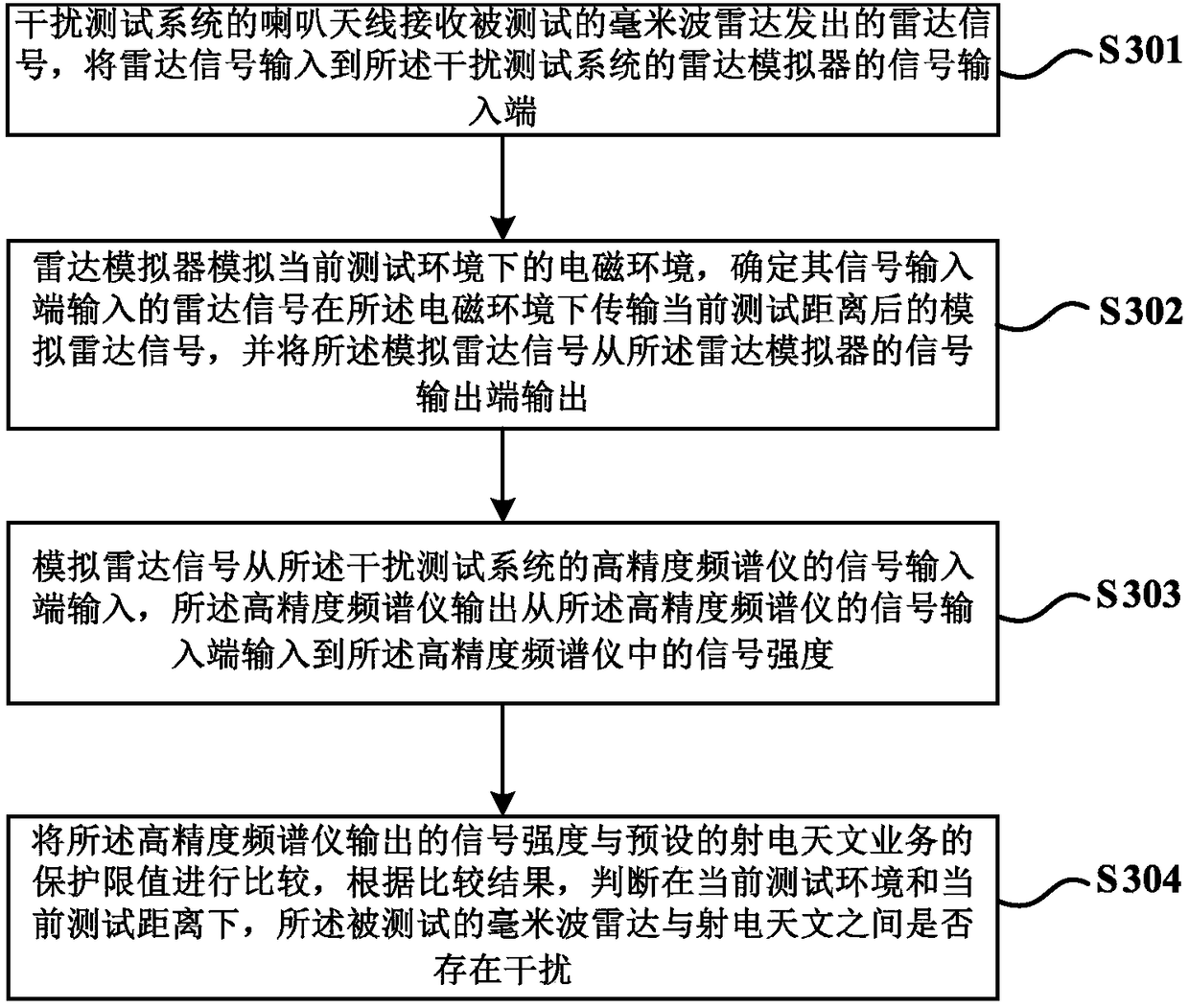
The invention provides an interference testing system between millimeter wave radar and radio astronomy. The interference testing system comprises an electromagnetic shielding chamber, a horn antenna,a radar simulator and a high-precision frequency spectrograph, wherein the horn antenna is matched with the frequency band of the tested millimeter wave radar, is arranged in the electromagnetic shielding chamber and is opposite to the millimeter wave radar; the distance between the horn antenna and the tested millimeter wave radar is smaller than a preset value; the radar simulator is arranged in the electromagnetic shielding chamber; the signal input end of the radar simulator is connected with the horn antenna and is used for simulating an electromagnetic environment in a current testing environment and current testing distance; the high-precision frequency spectrograph is arranged in the electromagnetic shielding chamber; the signal input end of the high-precision frequency spectrograph is connected with the signal output end of the radar simulator; the high-precision frequency spectrograph is used for simulating the radio astronomy and outputs signal intensity inputted from the signal input end of the high-precision frequency spectrograph to the high-precision frequency spectrograph. The interference testing system between the millimeter wave radar and the radio astronomy, provided by the invention, has the advantages that complexity and high possibility of making errors for obtaining the result are reduced, and a large amount of consumption of labor force and physical force in an actual external field test is avoided.

Description

Technical field [0001] The invention relates to the technical field of intelligent transportation applications, in particular to an interference test system between millimeter wave radar and radio astronomy. Background technique [0002] Advanced Driver Assistant Systems (ADAS, Advanced Driver Assistant Systems) uses various sensors installed in the car to continuously perceive the surrounding environment and collect data during the driving process of the car to identify, detect and track static and dynamic objects, and Combining with the map data of the navigator, the calculation and analysis of the system are carried out, so that the driver can be aware of possible dangers in advance, and effectively increase the comfort and safety of car driving. The sensors used in ADAS mainly include cameras, radars, lasers and ultrasonics, which can detect light, heat, pressure or other variables used to monitor the state of the car. They are usually located at the front and rear, sides, co...

Claims


Application Information

Patent Timeline
Patent Type & Authority Applications(China)
IPC IPC(8): G01S7/40
CPCG01S7/40
Inventor 杨渊房骥刘瑞婷刘晓勇许瑞琛彭潇武文星付靖
Owner THE STATE RADIO MONITORING CENT TESTING CENT
Learn More