
Exposure Rotary Fixture

A fixture and rotating shaft technology, applied in microlithography exposure equipment, photolithography exposure equipment, etc., can solve the problems of reducing operating efficiency, not meeting production efficiency, and increasing the burden of manpower

Active Publication Date: 2019-11-26
INTERFACE TECH CHENGDU CO LTD +2
View PDF4 Cites 0 Cited by
  • Summary
  • Abstract
  • Description
  • Claims
  • Application Information

AI Technical Summary

Problems solved by technology

[0002] When the produced substrate is to be subjected to UV exposure, it is necessary to expose multiple parts of the substrate. However, the existing jig mechanism can only be used to position the substrate. When the light source is activated, it can only expose a part of the substrate in a single direction. If you want to expose the entire substrate, you need to take out the substrate from the jig mechanism, and put it back into the jig mechanism after changing the angle of the substrate (such as rotating the substrate) to change the exposure position of the substrate. It is necessary to disassemble and install the substrate many times. Complete the substrate's requirements for the exposure process
In addition, every time the exposure direction is changed, different fixture mechanisms need to be replaced, resulting in repeated loading and unloading of the substrate, which is easy to be damaged, reduces the efficiency of the operation, and increases the burden of manpower, which is not in line with the benefits of production

Method used


Image

  • Exposure Rotary Fixture
  • Exposure Rotary Fixture
  • Exposure Rotary Fixture

Examples


Embodiment Construction

[0052] The following will disclose multiple implementations of the present disclosure with diagrams, and for the sake of clarity, many practical details will be described together in the following description. However, it should be understood that these practical details should not be used to limit the present disclosure. That is to say, in some embodiments of the present disclosure, these practical details are unnecessary. In addition, for the sake of simplifying the drawings, some commonly used structures and components will be shown in a simple and schematic manner in the drawings.

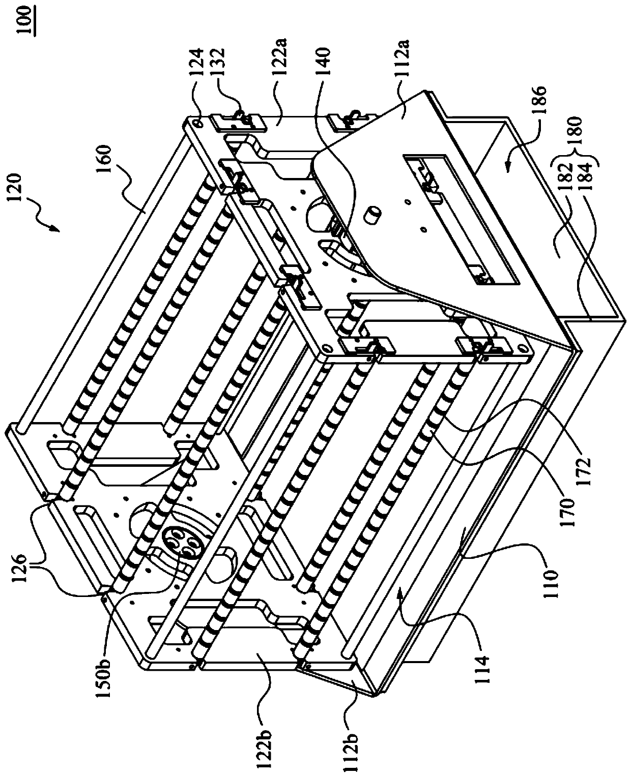
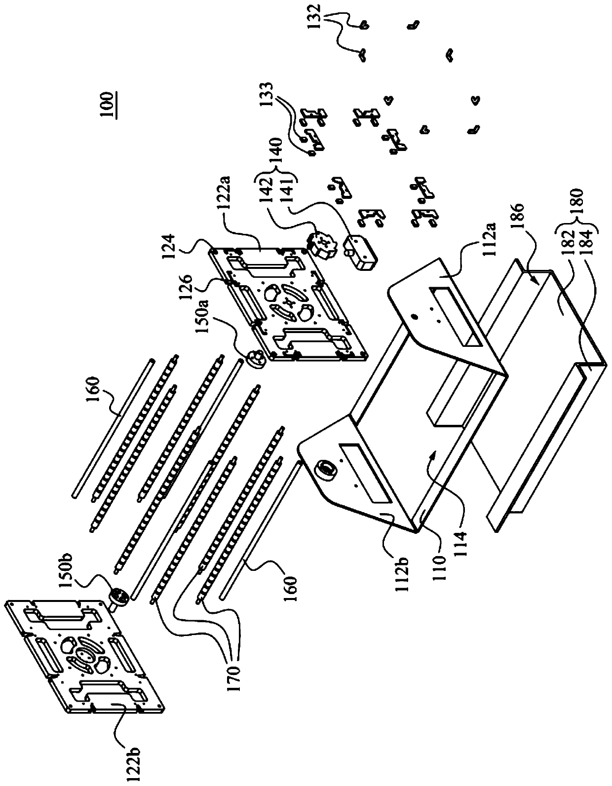
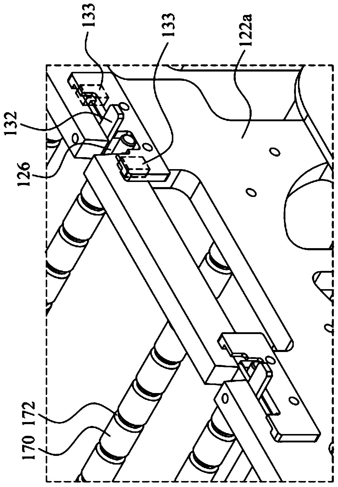
[0053] figure 1 It is a perspective view of an exposure rotary fixture 100 according to an embodiment of the present disclosure. figure 2 for figure 1 An exploded view of the exposure rotary jig 100. see also figure 1 and figure 2 , the exposure rotary fixture 100 includes a support frame 110 and a containing component 120 . The supporting frame 110 has two opposite positioning plates ...


PUM


Abstract

The invention discloses a rotary jig for exposure. The rotary jig comprises a support frame and an accommodating assembly, wherein the support frame is provided with two opposite positioning plates; the accommodating assembly is rotationally arranged on the inner sides of the two positioning plates and comprises two inner frame plates, a ratchet mechanism, two rotating shafts, a plurality of fixedshafts and a plurality of clamping strips; the two inner frame plates are located on the inner sides of the two positioning plates; the ratchet mechanism is located between one of the two inner frameplates and one of the two positioning plates. The rotating shafts penetrate through the two inner frame plates and the two positioning plates, and one of the two rotating shafts penetrates through the ratchet mechanism; two ends of each fixed shaft are fixed at corners of the two inner frame plates respectively. Each clamping strip is detachably bridged on the two inner frame plates. The ratchetmechanism can allow the accommodating assembly to rotate on the support frame at multiple positioning angles, and therefore, multiple parts of a substrate can be exposed on the premise that the substrate is not taken down in the exposure process. The rotary jig for exposure can increase the output efficiency and the cost of the jig can be reduced.

Description

technical field [0001] The present disclosure relates to an exposure rotary jig. Background technique [0002] When the produced substrate is to be subjected to UV exposure, it is necessary to expose multiple parts of the substrate. However, the existing jig mechanism can only be used to position the substrate. When the light source is activated, it can only expose a part of the substrate in a single direction. If you want to expose the entire substrate, you need to take out the substrate from the jig mechanism, and put it back into the jig mechanism after changing the angle of the substrate (such as rotating the substrate) to change the exposure position of the substrate. It is necessary to disassemble and install the substrate many times. Complete the requirements of the substrate for the exposure process. In addition, each time the exposure direction is changed, different jig mechanisms need to be replaced, resulting in repeated loading and unloading of the substrate, wh...

Claims


Application Information

Patent Timeline
Patent Type & Authority Patents(China)
IPC IPC(8): G03F7/20
CPCG03F7/20
Inventor 吴德
Owner INTERFACE TECH CHENGDU CO LTD
Learn More