Organisches Leuchtbauelement

Inactive Publication Date: 2008-06-19
NOVALED AG
View PDF61 Cites 32 Cited by
  • Summary
  • Abstract
  • Description
  • Claims
  • Application Information

AI Technical Summary

Benefits of technology

[0019]The object of the invention is to provide an improved organic lighting component of the type described at the outset, in which the above-described problems of the prior art are avoided.
[0020]This object is achieved according to the invention by use of an organic lighting component according to independent claim 1. Advantageous refinements of the invention are the subject matter of the dependent subclaims.
[0021]The concept of the invention is to provide an organic lighting component, in particular an organic light-emitting diode, comprising a lighting element and a luminous surface encompassed by the lighting element, the luminous surface being formed by an electrode, a counterelectrode, and an organic layer system which is situated between the electrode and the counterelectrode and is in electrical contact with the electrode and the counterelectrode. Sections of the organic layer system which are located in the region of the luminous surface and which emit light upon application of an electrical voltage to the electrode and the counterelectrode have a uniform organic material structure and are provided on multiple partial electrodes of the electrode electrically connected in parallel, in which a lateral distance between adjacent partial electrodes is smaller than the width of the adjacent partial electrodes. In this context, a uniform organic material structure of the organic layer system in the sections on the partial electrodes connected in parallel means that light of the same color is emitted due to the similar material composition. The light may have any given color of the visible spectrum. Each of the individual sections may include emitter materials which emit light of various colors, which is then mixed for each individual section to form a mixed light in particular white light.
[0022]The provided structural design of the multiple partial electrodes of the electrode electrically connected in parallel has the advantage that the output efficiency of the overall organic lighting components remains high when, for example, a localized electrical short circuit occurs in the vicinity of one of the partial electrodes. The optical appearance of the lighting component during operation remains substantially sat

Problems solved by technology

However, significant technical problems must still be solved for a successful commercialization of the technology for organic lighting components.
A particular challenge is the use of OLED components to generate large quantities of light necessary for general lighting applications.
The brightness of an organic lighting component cannot be arbitrarily increased.
However, supplying an organic lighting component with such a current represents a considerable technical problem which is not readily solved in an economical manner in commercial lighting applications.
If larger component surfaces are needed the supply current would have to be further increased, thus intensifying the problems with the power supply.
However, producing OLED lighting components having a series connection of OLED lighting elements requires a complex manufacturing process.
However, the LITT method may be used only for structuring of the organic layer system of the OLED lighting elements.
The structuring methods involve significant complexity in manufacturing the organic lighting component, resulting in high costs.
When shadow masks are used, there is the additional problem of limited resolution; i.e., the distance between the OLED lighting elements connected in series is limited by the dimensions of the webs of the shadow mask.
Furthermore, the use of shadow masks is a limiting factor with regard to the achievable processing times, since fin

Method used


Image

  • Organisches Leuchtbauelement
  • Organisches Leuchtbauelement

Examples


Example

[0045]The invention is explained in greater detail below with reference to preferred exemplary embodiments, with reference to a drawing, which shows the following:

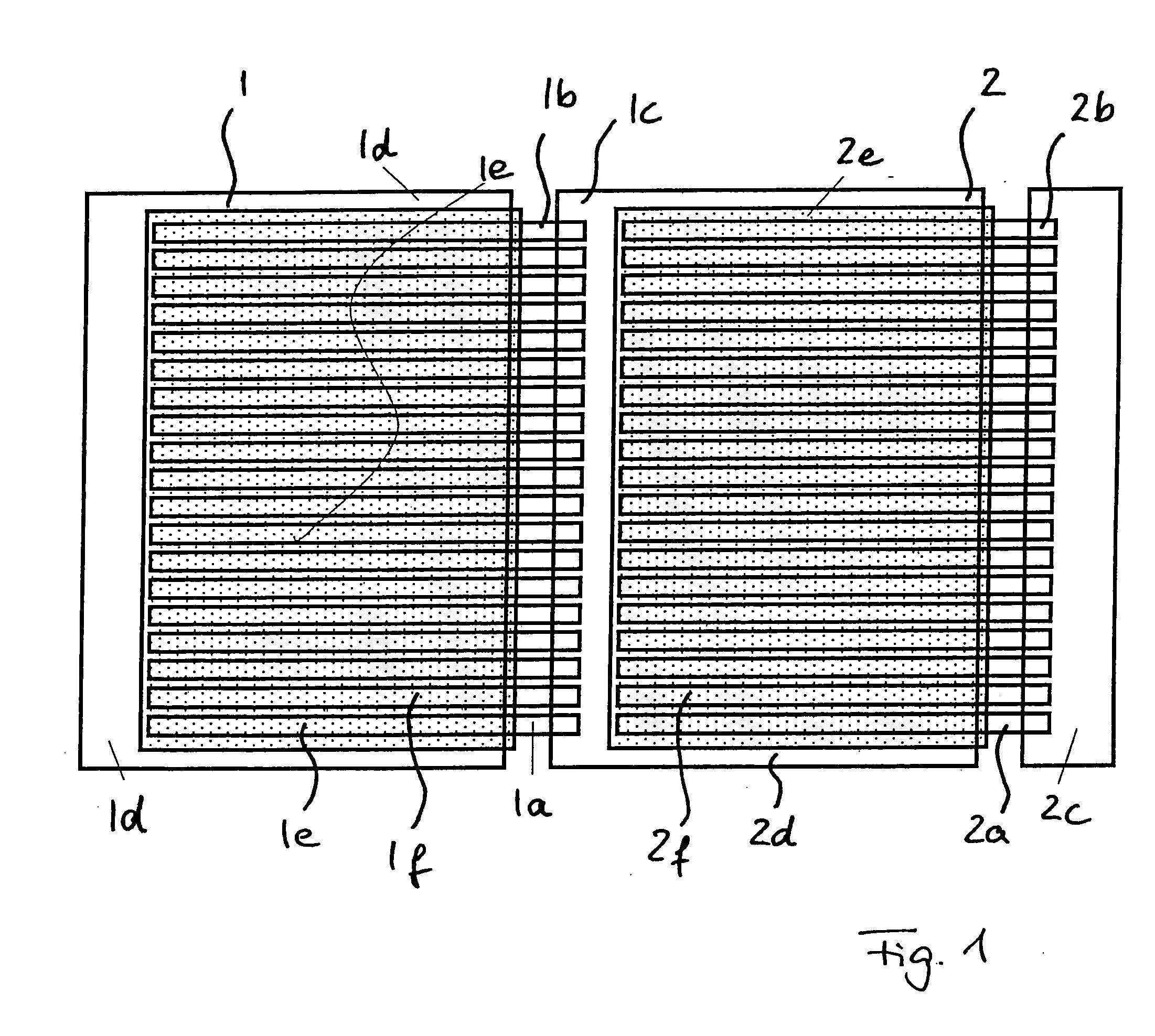
[0046]FIG. 1 shows a schematic illustration of an organic lighting component having two lighting elements electrically connected in series; and

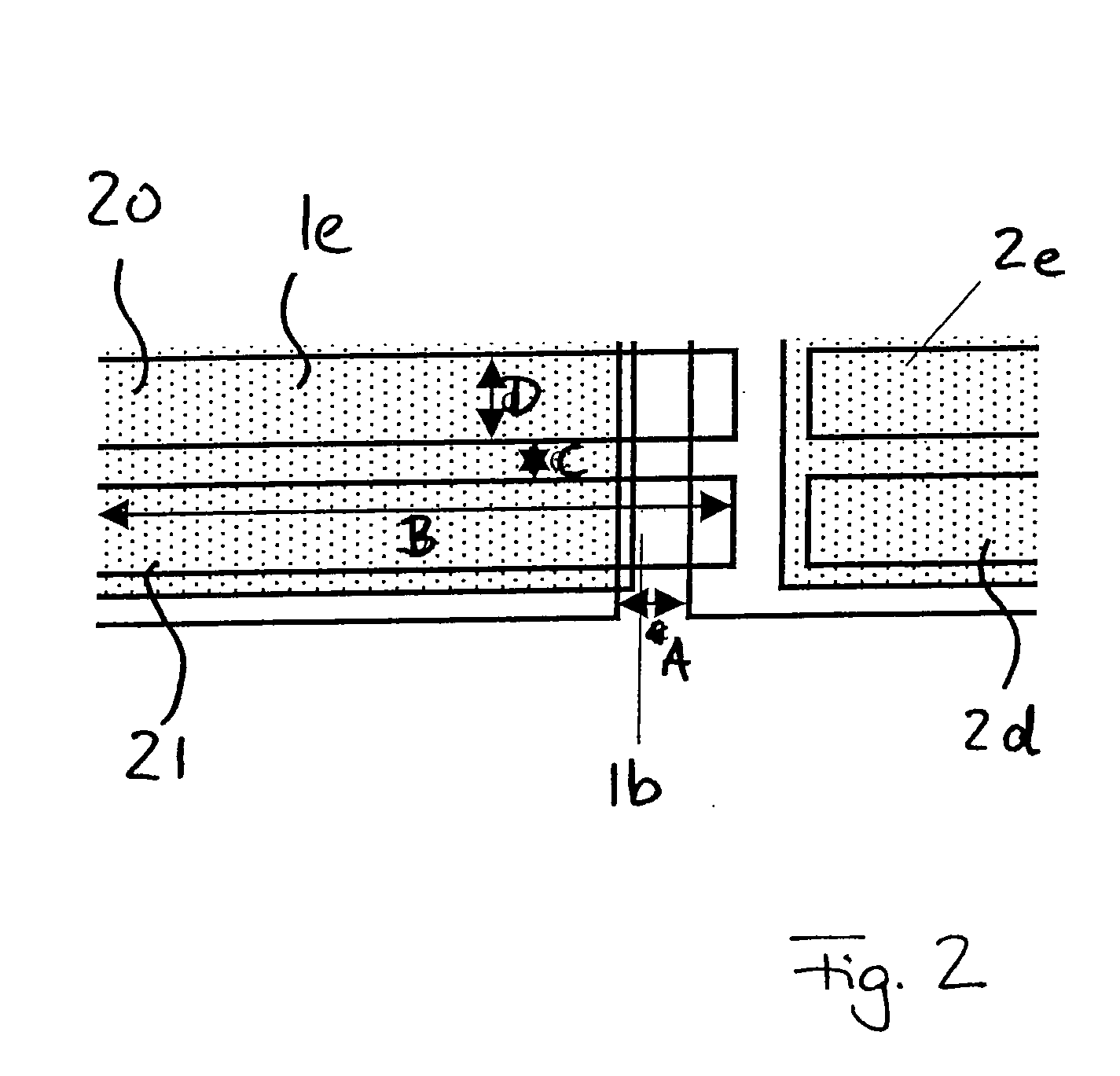
[0047]FIG. 2 shows an enlarged illustration of a section of the organic lighting component according to FIG. 1.

[0048]FIG. 1 shows a schematic illustration of an organic lighting component having two lighting elements 1, 2 electrically connected in series. Each of the two lighting elements 1, 2 has an electrode 1a, 2a which is provided as a configuration of multiple strip-shaped partial electrodes 1b, 2b extending in parallel. The partial electrodes 1b, 2b are each connected to a contact connection 1c, 2c, and are thus electrically connected in parallel. In addition, the two lighting elements 1, 2 each have a counterelectrode 1d, 2d which is provided as a flat electrode. In one simpl...


PUM


Abstract

The invention relates to an organic lighting component, in particular an organic light-emitting diode, comprising a lighting element (1; 2) and a luminous surface (1f, 2f) encompassed by the lighting element (1; 2), the luminous surface being formed by an electrode (1a; 2a), a counterelectrode (1d; 2d), and an organic layer system (1e; 2e) which is situated between the electrode (1a; 2a) and the counterelectrode (1d; 2d) and is in electrical contact with the electrode (1a; 2a) and the counterelectrode (1d; 2d), wherein sections of the organic layer system (1e; 2e) which are located in the region of the luminous surface (1f; 2f) and which emit light upon application of an electrical voltage to the electrode (1a; 2a) and the counterelectrode (1d; 2d) have a uniform organic material structure and are provided on multiple partial electrodes (1b; 2b) of the electrode (1a; 2a) electrically connected in parallel, on one side the multiple partial electrodes being electrically connected to one another at their ends, and in which a lateral distance between adjacent partial electrodes (1b; 2b) is smaller than the width of the adjacent partial electrodes (1b; 2b).

Description

[0001]The invention relates to an organic lighting component, in particular an organic light-emitting diode, comprising a lighting element and a luminous surface encompassed by the lighting element.BACKGROUND OF THE INVENTION[0002]Organic lighting components in the form of organic light-emitting diodes (OLEDs) which emit colored light, in particular white light, have received increased attention in recent years. It is generally known that the technology of organic lighting components has a great potential for possible applications in the field of lighting technology. In the meantime, organic light-emitting diodes have attained output efficiencies in the range of conventional electric incandescent bulbs (see Forrest et al., Adv. Mat. 7 (2004) 624).[0003]Organic light-emitting diodes are usually produced by means of a layered structure which is provided on a substrate. An organic layer system is situated in the layered structure between an electrode and a counterelectrode, so that the...

Claims


Application Information

Patent Timeline
IPC IPC(8): H01L27/28
CPCH01L27/3202H01L27/3204H01L2251/5361H01L51/5268H01L51/5203H10K59/84H10K59/86H10K50/805H10K50/854H05B33/26
Inventor BLOCHWITZ-NIMOTH, JANMURANO, SVENBIRNSTOCK, JAN
Owner NOVALED AG
Why Eureka
Try Eureka