
Projector for high school teaching

A technology for projectors and high school students, applied in the field of projectors, can solve the problems that the installation distance and angle of the projector rack cannot be changed, it is inconvenient for the installer to install the equipment, and the projector is inconvenient to disassemble, etc., so as to achieve simple structure and good use effect , the effect of structural stability

Inactive Publication Date: 2018-06-29
四川乐为科技有限公司
View PDF0 Cites 1 Cited by
  • Summary
  • Abstract
  • Description
  • Claims
  • Application Information

AI Technical Summary

Problems solved by technology

[0002] A projector is an optical instrument that uses optical components to enlarge the outline of a workpiece and project it onto a video screen. In the early 20th century, projectors were widely used as teaching tools in high school teaching. The main installation methods of projectors are ceiling and Wall-mounted; the existing projectors have certain disadvantages in use. The installation of the projector requires very accurate distance calculation, and the installation distance will also change according to the size of the classroom. The existing projector is very cumbersome. It is convenient for the installer to install the equipment. The bulb of the projector needs to be replaced and cleaned frequently, but the traditional projector hanger is not easy to disassemble. The installation distance and angle of the projector hanger are fixed and cannot be changed, which is very inconvenient for schools. The use of the projector has brought some influence, for this reason, we propose a kind of projector for high school students

Method used


Image

  • Projector for high school teaching
  • Projector for high school teaching
  • Projector for high school teaching

Examples


Embodiment Construction

[0018] In order to make the technical means, creative features, goals and effects achieved by the present invention easy to understand, the present invention will be further described below in conjunction with specific embodiments.

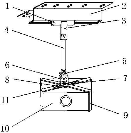
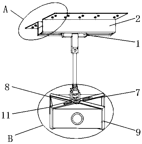
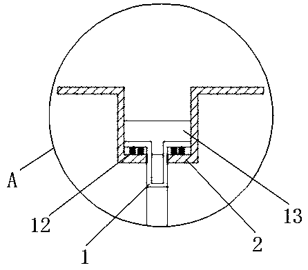
[0019] Such as Figure 1-5 As shown, a projector for teaching high school students includes a sliding connection seat 1 and a fixed disc 7, the outer upper end of the sliding connection seat 1 is movably installed with a ceiling mounting frame 2, and the lower end of the outer surface of the sliding connection seat 1 is fixedly installed There is a linear driver 3, and the lower end of the outer surface of the sliding connection seat 1 is provided with a driving telescopic rod 4 at the lower end of the outer surface of the linear driver 3, and a baffle plate is fixedly installed on both ends of the outer surface of the ceiling mounting frame 2 on the outer upper end of the sliding connection seat 1 13. A pulley 12 is movably installed between the ...


PUM


Abstract

The invention discloses a projector for high school teaching. The projector comprises a slide connection seat and a fixed disc, wherein a ceiling mounting rack is movably mounted at the upper end of the outer surface of the slide connection seat, a linear actuator is fixedly mounted at the lower end of the outer surface of the slide connection seat, a drive telescopic rod is arranged at the lowerend of the outer surface of the linear actuator at the lower end of the outer surface of the slide connection seat, baffle plates are fixedly mounted at two ends of the outer surface of the ceiling mounting rack at the upper end of the outer surface of the slide connection seat, and pulleys are movably mounted between the lower end of the outer surface of the slide connection seat and the bottom end of the inner surface of the ceiling mounting rack. The projector for high school teaching provided with the slide connection seat, a right-angled movable rack and magnetic clasps can be conveniently installed by an installer, can move forwards, backwards, upwards and downwards, can be taken down easily at any time for cleaning or replacement, adapts to different working conditions and has better application prospect.

Description

technical field [0001] The invention relates to the field of projectors, in particular to a projector used for teaching high school students. Background technique [0002] A projector is an optical instrument that uses optical components to enlarge the outline of a workpiece and project it onto a video screen. In the early 20th century, projectors were widely used as teaching tools in high school teaching. The main installation methods of projectors are ceiling and Wall-mounted; the existing projectors have certain disadvantages in use. The installation of the projector requires very accurate distance calculation, and the installation distance will also change according to the size of the classroom. It is convenient for the installer to install the equipment. The bulb of the projector needs to be replaced and cleaned frequently, but the traditional projector hanger is not easy to disassemble. The installation distance and angle of the projector hanger are fixed and cannot be...

Claims


Application Information

Patent Timeline
IPC IPC(8): G09B5/02G03B21/54
CPCG09B5/02G03B21/54
Inventor 程飞
Owner 四川乐为科技有限公司
Learn More