Separable front dust removal tank of flue gas purification equipment

A technology of flue gas purification and dust removal box, which is applied in the direction of separation method, dispersed particle separation, dispersed particle filtration, etc., can solve the problems of waste of resources, difficulty in filter replacement, etc., and achieve the effect of easy cleaning and replacement

Inactive Publication Date: 2017-06-27
JIANGSU ZIQIANG COATING MACHINERY
View PDF0 Cites 7 Cited by
  • Summary
  • Abstract
  • Description
  • Claims
  • Application Information

AI Technical Summary

Problems solved by technology

[0003] The main harmful components in the exhaust gas emitted by industrial processes include dust, sulfur oxides, nitrogen oxides, nitrates, etc. at the same concentration; at present, the dust is mainly treated by adsorption. For large factories, the exhaust gas is much, and the adsorption treatment The equipment usually places multiple rows of large filter screens in the large box, and the exhaust gas passes through the multiple rows of filter screens to absorb the dust; therefore, it is difficult to replace the filter screen. Usually, large auxiliary equipment is used to replace the filter screen. Hang out from the box, clean and replace the filter and put it back into the large box; and the existing dust removal equipment is directly connected to the subsequent exhaust gas treatment equipment, and the factory will replace the product. If the pollution degree in the exhaust gas is not high When the dust removal rate is high, the emission requirements can be met only through adsorption treatment of the flue gas. If directly connected and inseparable dust removal equipment is used, it will cause excessive waste of resources.

Method used


Image

  • Separable front dust removal tank of flue gas purification equipment
  • Separable front dust removal tank of flue gas purification equipment
  • Separable front dust removal tank of flue gas purification equipment

Examples


Embodiment Construction

[0028] Below in conjunction with accompanying drawing and embodiment of description, specific embodiment of the present invention is described in further detail:

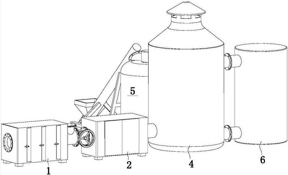
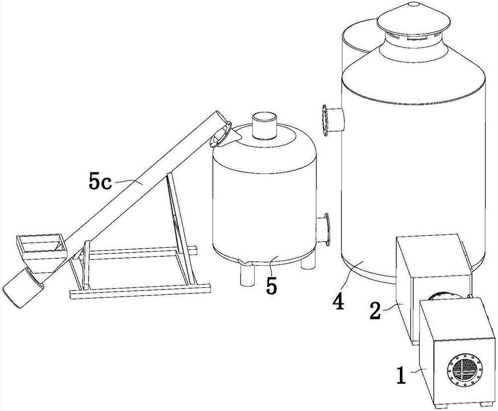
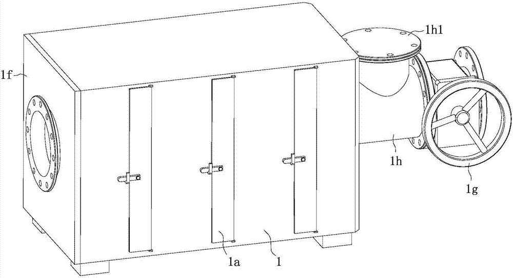
[0029] according to Figure 1 to Figure 11 The exhaust gas comprehensive treatment equipment shown includes a dust removal box 1, photocatalyst exhaust gas treatment equipment and desulfurization and denitrification equipment. The left and right ends of the dust removal box 1 are respectively provided with connecting flanges, and the dust removal box 1 extends the straight line connecting the flanges at both ends. There are multiple rows of activated carbon filters evenly distributed in the direction; the photocatalyst waste gas treatment equipment includes a box body 2, the two ends of the box body 2 are respectively provided with connecting flanges, the box body 2 and the dust removal box 1 are connected by pipelines, and the inner extension There are many rows of honeycomb panels distributed in the straight line ...


PUM

PropertyMeasurementUnit
heightaaaaaaaaaa
heightaaaaaaaaaa

Abstract

The invention relates to the field of waste gas treatment equipment, in particular to a separable front dust removal tank of flue gas purification equipment. The separable front dust removal tank comprises connecting flanges. The connecting flanges are arranged at the left end and the right end of a dust removal tank, the dust removal tank is provided with a plurality of rows of activated carbon filter screens which are uniformly distributed along the linear directions of the connecting flanges at the two ends of the dust removal tank, and the activated carbon filter screens are matched with the dust removal tank in an insertion manner; maintenance doors are arranged on a front side plate of the dust removal tank, and each maintenance door corresponds to the corresponding row of activated carbon filter screens; each row of activated carbon filter screens comprises an upper filter screen, a middle filter screen and a lower filter screen which are sequentially overlaid on one another in the up-down directions, first supports are arranged in the dust removal tank, each first support corresponds to the corresponding row of activated carbon filter screens, and the upper filter screens, the middle filter screens and the lower filter screens are inserted into the first supports from openings in the sides of the first supports and are lapped on the first supports. The separable front dust removal tank has the advantage that three small filter screens are arranged in the dust removal tank and accordingly are convenient to clean and replace.

Description

technical field [0001] The invention relates to the field of exhaust gas treatment equipment, in particular to a detachable front dust removal box of flue gas purification equipment. Background technique [0002] Exhaust gas purification mainly refers to the work of treating industrial waste gas such as dust particles, flue gas smoke, odorous gas, and toxic and harmful gases generated in industrial places. [0003] The main harmful components in the exhaust gas emitted by industrial processes include dust, sulfur oxides, nitrogen oxides, nitrates, etc. at the same concentration; at present, the dust is mainly treated by adsorption. For large factories, the exhaust gas is much, and the adsorption treatment The equipment usually places multiple rows of large filter screens in the large box, and the exhaust gas passes through the multiple rows of filter screens to absorb the dust; therefore, it is difficult to replace the filter screen. Usually, large auxiliary equipment is use...

Claims


Application Information

Patent Timeline
Patent Type & Authority Applications(China)
IPC IPC(8): B01D46/12
CPCB01D46/0006B01D46/0008B01D46/0036B01D46/12B01D46/60
Inventor 吕琳吕海波张林俊孙晋东郝正浩宋友高
Owner JIANGSU ZIQIANG COATING MACHINERY
Why Eureka
Try Eureka