
LED display module provided with memory units and control method of LED display module

A storage unit and display module technology, applied in information storage, static memory, digital memory information, etc., can solve the problems of high labor cost, large dependence on labor, difficult early operation, etc., and achieve simple and convenient use and save back The effect of saving space and simplifying the installation and commissioning process

Pending Publication Date: 2018-06-29
FUJIAN QIANGLI PHOTOELECTRICITY
View PDF10 Cites 4 Cited by
  • Summary
  • Abstract
  • Description
  • Claims
  • Application Information

AI Technical Summary

Problems solved by technology

This kind of LED display module relies heavily on labor, and requires special debugging personnel or training for users, which leads to difficulties in early operation and high labor costs.

Method used


Image

  • LED display module provided with memory units and control method of LED display module
  • LED display module provided with memory units and control method of LED display module
  • LED display module provided with memory units and control method of LED display module

Examples


Embodiment 1

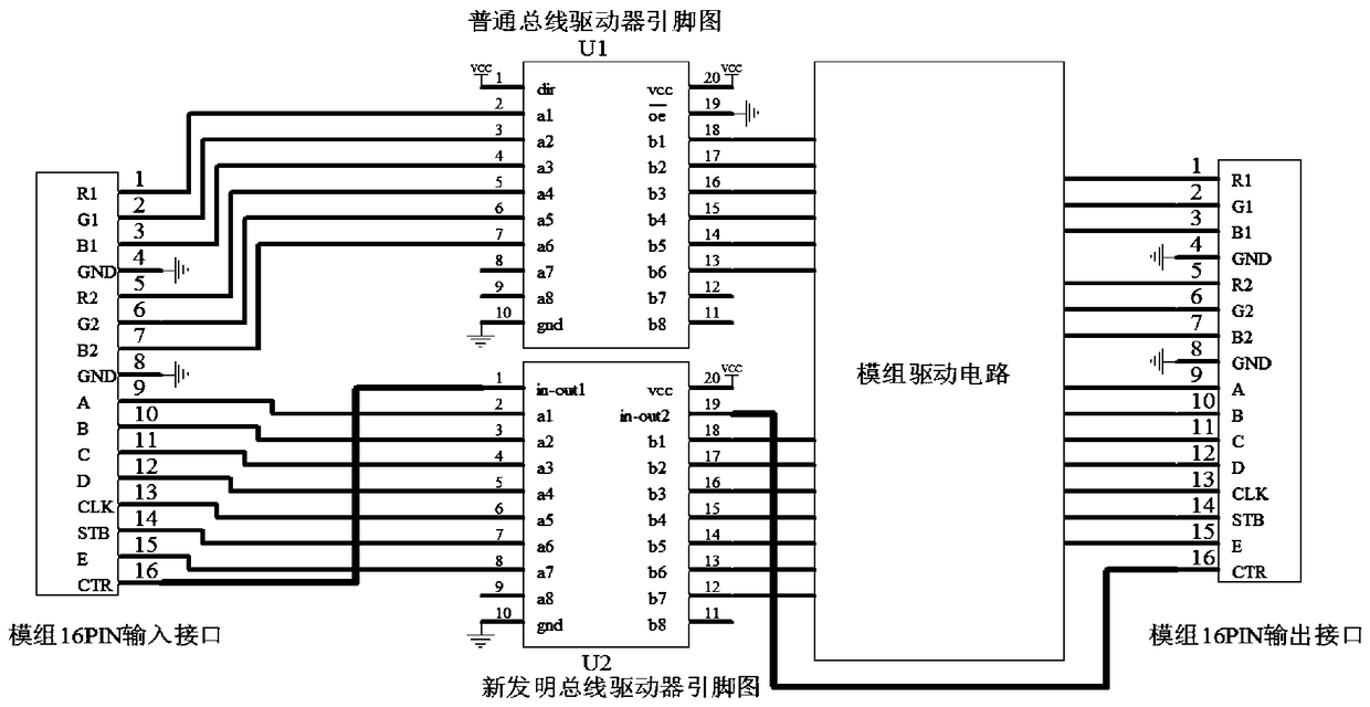
[0032] Embodiment 1, the storage unit is arranged in parallel with the bus driver, and the input interface is provided with an interface corresponding to each pin of the storage unit; when the display units are cascaded in sequence, each of the display units The corresponding storage units are also cascaded in sequence, wherein the data interfaces of the cascaded multiple storage units are sequentially connected in parallel and then connected to the corresponding interfaces on the input interface, and the clock interfaces of the cascaded multiple storage units The corresponding interfaces on the input interfaces are connected in parallel sequentially, and the chip select interfaces of the cascaded multiple storage units are respectively connected to corresponding interfaces on the input interfaces. The present invention adds a device with a storage function on the basis of the existing LED display module, which is used to store the relevant parameter information of the LED disp...

Embodiment 2

[0033]Embodiment 2, this embodiment is basically the same as Embodiment 1, the difference is: further, the storage unit is integrated in the bus driver, and the bus driver includes a first input and output terminal (IN-OUT1) and the second input and output terminal (IN-OUT2), the first input and output terminal (IN-OUT1) of the bus driver and the data transmission terminal on the same side as the first input and output terminal (IN-OUT1) are all connected to the The input interface is connected, the second input and output terminal (IN-OUT2) of the bus driver is connected to the output interface, and the data transmission terminal on the same side as the second input and output terminal (IN-OUT2) is connected to the module The group drive circuits are connected; in the cascaded state, the output interface of the previous display unit is connected to the input interface of the next display unit.

[0034] the memory cells are enclosed in the bus driver integrated circuit package...


PUM


Abstract

The invention provides an LED display module provided with memory units and a control method of the LED display module. Devices with the memory function are added on the basis of the conventional LEDdisplay module and used for storing relevant parameter information of the LED display module, so that the parameters are read automatically when the LED display module is connected with a control system, and parameter setting is completed automatically; after completion of the automatic setting, the control system sends display data automatically for normal display; therefore, automatic identification and display of the LED display module are realized. The LED display module comprises a plurality of display units in sequential cascade connection as well as memory units, wherein each display unit comprises an input interface, a bus driver, a module drive circuit and an output interface which are electrically connected in sequence; each memory unit comprises a memory, and the memory and thecorresponding bus driver are connected in parallel between the corresponding input interface and the corresponding module drive circuit; or, each memory unit is integrated in the corresponding bus driver.

Description

technical field [0001] The invention relates to the field of LED display screens, in particular to an LED display module with a storage unit and a control method thereof. Background technique [0002] Existing LED display modules are usually electronic circuit products composed of data interfaces, circuit driver ICs, LED light-emitting diodes (light tubes), etc. LED display modules with different specifications, their lamp tubes, driver ICs, scanning methods, data The transmission mode, refresh rate, gray level and other parameters are different; due to the difference of these parameters, it is necessary to manually input each parameter in the application, and the LED display module can display correctly after the parameters are set. This kind of LED display module relies heavily on labor, and requires special debugging personnel or training for users, which leads to difficulties in early operation and high labor costs. Contents of the invention [0003] The invention pro...

Claims


Application Information

Patent Timeline
Patent Type & Authority Applications(China)
IPC IPC(8): G09G3/32G11C7/10
CPCG09G3/32G11C7/1006G11C7/1048
Inventor 杨树军徐惠能朱卫平
Owner FUJIAN QIANGLI PHOTOELECTRICITY
Learn More