Coil framework and binding post connecting structure and mounting method thereof

A coil skeleton and connection structure technology, applied in the direction of electromagnetic terminals/connectors, electrical components, electromagnets, etc., can solve the problems of easy bending of the terminal, short circuit between the circuit board and the coil, and easy loosening of the terminal, so as to prevent short circuit , the effect of increasing the installation distance

Pending Publication Date: 2018-06-29
宁波市鄞州通力液压电器厂
View PDF0 Cites 1 Cited by
  • Summary
  • Abstract
  • Description
  • Claims
  • Application Information

AI Technical Summary

Problems solved by technology

[0002] Solenoid valve is electromagnetically controlled industrial equipment, which is an automatic basic component used to control fluid. It uses coil to flow current to generate magnetic field, so the electromagnet is wound with coil, and the coil is wound on the coil skeleton by winding machine, and the coil skeleton There is also a terminal made of metal for connecting the coil and the circuit board, but the connection structure between the existing coil skeleton and the terminal is relatively simple. After a long period of use, the terminal is easy to loosen, and the terminal is easy to bend after loosening , the contact with the coil after bending down is easy to damage the protective layer of the wire and cause a short circuit. In addition, because the upper end of the terminal is welded to the circuit board, the market generally positions the soldered circuit board directly on the upper end of the coil skeleton, which makes the circuit board Too close to the coil is prone to short circuit, and there is a big hidden danger of safe work

Method used


Image

  • Coil framework and binding post connecting structure and mounting method thereof
  • Coil framework and binding post connecting structure and mounting method thereof
  • Coil framework and binding post connecting structure and mounting method thereof

Examples


Embodiment Construction

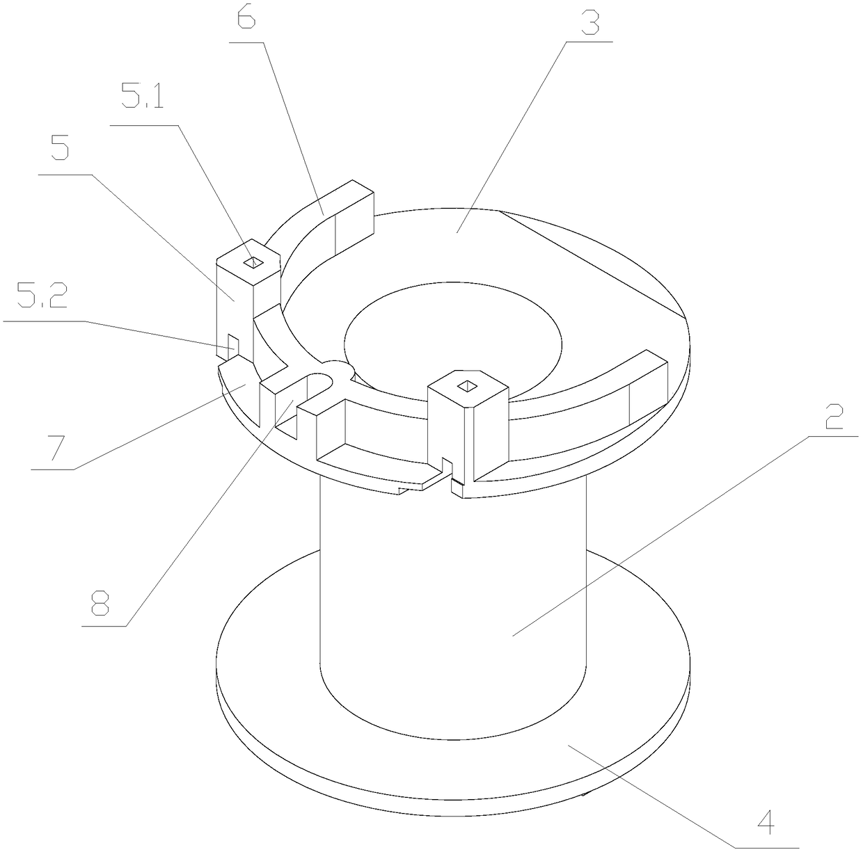
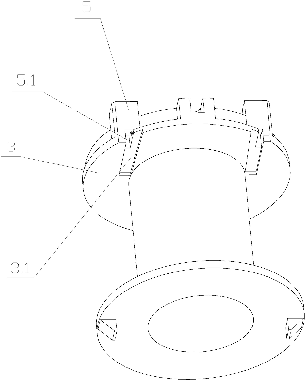
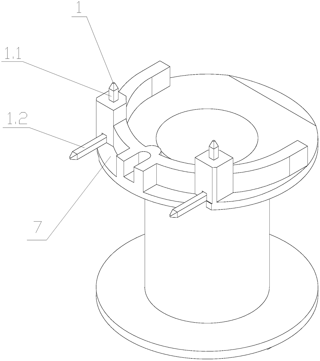
[0021] Such as Figure 1-4 As shown, a connection structure between a coil bobbin and a terminal, including a coil bobbin and a terminal 1, the coil bobbin includes a cylindrical winding part 2 for winding a wire, and the upper end of the winding part 2 is provided with a first platform part 3. The lower end of the winding part 2 is provided with a second platform part 4, the terminal post 1 is connected to the first platform part 3, and the first platform part 3 is protruded with a pluggable terminal part 1 vertically The mounting part 5 of section 1.1, the first platform part 3 is also protruded with a rib 6, the distance from the outer side of the rib 6 to the edge of the first platform part 3 is greater than zero, and the outer side of the rib 6 and the first platform part 3 A receiving groove 7 that can support the horizontal section 1.2 of the terminal post 1 is formed. The arrangement of the installation part 5 and the accommodating groove 7 forms a positioning and supp...


PUM


Abstract

The invention relates to a coil framework and binding post connecting structure and a mounting method thereof. The connecting structure comprises a coil framework and a binding post, wherein the coilframework comprises a cylindrical winding part for winding wires; a first platform part is arranged at the upper end of the winding part; a second platform part is arranged at the lower end of the winding part; the binding post is connected onto the first platform part; a mounting part at which a vertical section of the binding post can be inserted is raised on the first platform part; a flange israised on the first platform part; the distance from the outer side of the flange to the edge of the first platform part is greater than zero; and a containing groove capable of supporting a horizontal section of the binding post is formed between the outer side of the flange and the first platform part. According to the connecting structure disclosed by the invention, the mounting part and the containing groove are arranged on the coil framework, so that the vertical section of the binding post is inserted into the mounting part, the horizontal section of the binding post is supported in thecontaining groove, the binding post is prevented from sliding upwards or downwards, and the condition that the binding post and the coil are contacted to damage a protective layer of the wire so as to cause short circuit is avoided.

Description

technical field [0001] The invention relates to the field of electromagnetic control industrial equipment, in particular to a connection structure between a coil frame and a terminal and an installation method thereof. Background technique [0002] Solenoid valve is electromagnetically controlled industrial equipment, which is an automatic basic component used to control fluid. It uses coil to flow current to generate magnetic field, so the electromagnet is wound with coil, and the coil is wound on the coil skeleton by winding machine, and the coil skeleton There is also a terminal made of metal for connecting the coil and the circuit board, but the connection structure between the existing coil skeleton and the terminal is relatively simple. After a long period of use, the terminal is easy to loosen, and the terminal is easy to bend after loosening , the contact with the coil after bending down is easy to damage the protective layer of the wire and cause a short circuit. In...

Claims


Application Information

Patent Timeline
Patent Type & Authority Applications(China)
IPC IPC(8): H01F7/02H01F41/00
CPCH01F7/02H01F41/00H01F2007/062
Inventor 刘晓林陈晓齐陈巍玲
Owner 宁波市鄞州通力液压电器厂
Why Eureka
Try Eureka