
Magnetic wire connecting device

A technology for wire connection and connection device, applied in the direction of conductive connection, connection, clamping/spring connection, etc., can solve problems such as difficulty in wire connection

Active Publication Date: 2018-06-29
CHINA PETROLEUM & CHEM CORP +1
View PDF5 Cites 0 Cited by
  • Summary
  • Abstract
  • Description
  • Claims
  • Application Information

AI Technical Summary

Problems solved by technology

[0003] The purpose of the present invention is to provide a convenient, quick and reliable magnetic wire connection device to solve the problem that the device structure often lacks wire connection points and makes wire connection difficult during temporary or long-term equipotential connection , without causing damage to the device structure

Method used


Image

  • Magnetic wire connecting device

Examples


Embodiment Construction

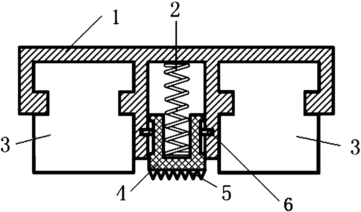
[0015] Below in conjunction with accompanying drawing, the present invention will be further described:

[0016] Such as figure 1 As shown, a magnetic wire connection device includes a frame 1, a magnet 3 fixed inside the frame 1, a spring 2 with one end contacting the frame 1, a crimping structure 4 connected to the other end of the spring 2, and a limiting crimping structure on the frame 1 4 A limit block 6 that moves in the direction of the symmetry axis of the frame 1 , and a sawtooth structure 5 fixed on the outer surface of the crimping structure 4 . The magnet fixes the conductor to be connected on the metal surface to be connected by magnetic force, and the magnet is in contact with the device to be connected. When the wiring works, the spring 2 crimps the wire and the device to be connected together through the crimping structure 4 and the sawtooth structure 5 . The pressure generated by the spring 2 and the sawtooth structure 5 is greater than the force of the conn...


PUM


Abstract

The invention belongs to the technical field of equipotential connection of wires, and discloses a magnetic wire connecting device. The magnetic wire connecting device comprises a frame, a magnet fixed inside the frame, a spring with one end being contacted with the frame, a crimping structure connected with the other end of the spring, a limiting block which limits the movement degree of the crimping structure in the symmetry axis direction of the frame on the frame and a sawtooth structure fixed at the outer surface of the crimping structure. When a wire connecting operation is performed, the spring crimps a wire and a device to be connected together through the crimping structure and the sawtooth structure. The magnetic wire connecting device quickly or temporarily crimps the wire to the device to be connected which does not have a wire connecting bolt so as to achieve electrical conduction between the wire and the device to be connected.

Description

technical field [0001] The invention relates to the technical field of wire equipotential connection, in particular to a magnetic wire connection device. Background technique [0002] In many cases, due to safety and technical requirements, we need to carry out some equipotential bonding, such as grounding of installations or metal structures. However, in the case of temporary or long-term equipotential connection, it often occurs that the device structure lacks wire connection points, which makes it difficult to connect the wires. For example, in order to reduce the damage of static electricity and lightning strikes, the outer surface of the oil and gas pipeline and the earth are effectively equipotentially connected. ; Temporary grounding of various test electrical equipment; Temporary grounding of the tanker body when loading and unloading oil. In order to complete the equipotential connection, threaded holes are usually processed on the device structure or the wire conn...

Claims


Application Information

Patent Timeline
IPC IPC(8): H01R4/48
CPCH01R4/4872
Inventor 姜辉刘全桢刘宝全高鑫毕晓蕾刘璇高剑张云朋
Owner CHINA PETROLEUM & CHEM CORP
Learn More