Stent

a technology of stents and stents, applied in the field of stents, can solve the problems of other constructions, inability to provide the necessary radial force, and oftentimes the support frame is not strong enough

Inactive Publication Date: 2010-04-06
QUALIMED INNOVATIVE MEDIZINPROD
View PDF13 Cites 9 Cited by
  • Summary
  • Abstract
  • Description
  • Claims
  • Application Information

AI Technical Summary

Benefits of technology

[0008]Based on the state of art, it is therefore an object of the invention to provide a stent with highest possible stability, in particular radial strength, while allowing good utilization of material.
[0010]This design is configured in such a manner that in support state of the stent, the immobile struts, which converge respectively with their ends in nodal points that act as friction-free joints, establish a type of self-stabilizing framework structure. Radial forces acting from outside to load the stent are absorbed in the nodal points and deflected there into the various strut directions. Thus, the stent according to the invention is characterized by a high stability and high radial strength. This can be utilized to reduce the material thickness and the strut width of the strut frame, resulting not only in a decrease of material use but in particular in a greater flexibility and better crimping capability of the stent as well as to a better restenosis rate, as existing studies have shown.
[0018]Overall, a frame support is realized with high radial stiffness in the support state. This ensures a very good and homogenous splinting of the vessel wall with a functionally suitable support. Still, a stent according to the invention is very easy to crimp and exhibits in this state a smooth flexible arrangement of the ring segments in the support frame. The stent can very easily be moved through the windings of a body vessel while being arranged on a balloon catheter for example. This smooth handling affords the user and the patient high safety during implantation.

Problems solved by technology

Practice has shown that the support frames oftentimes are either unable to provide the necessary radial forces to sufficiently resist a stenosis, or are so designed as to impede the function of the vessel.
Other constructions, in turn, cannot be sufficiently crimped or are not flexible enough, when crimped, in order to be able to reliably follow the body vessels and its turns.

Method used


Image

  • Stent
  • Stent
  • Stent

Examples


Embodiment Construction

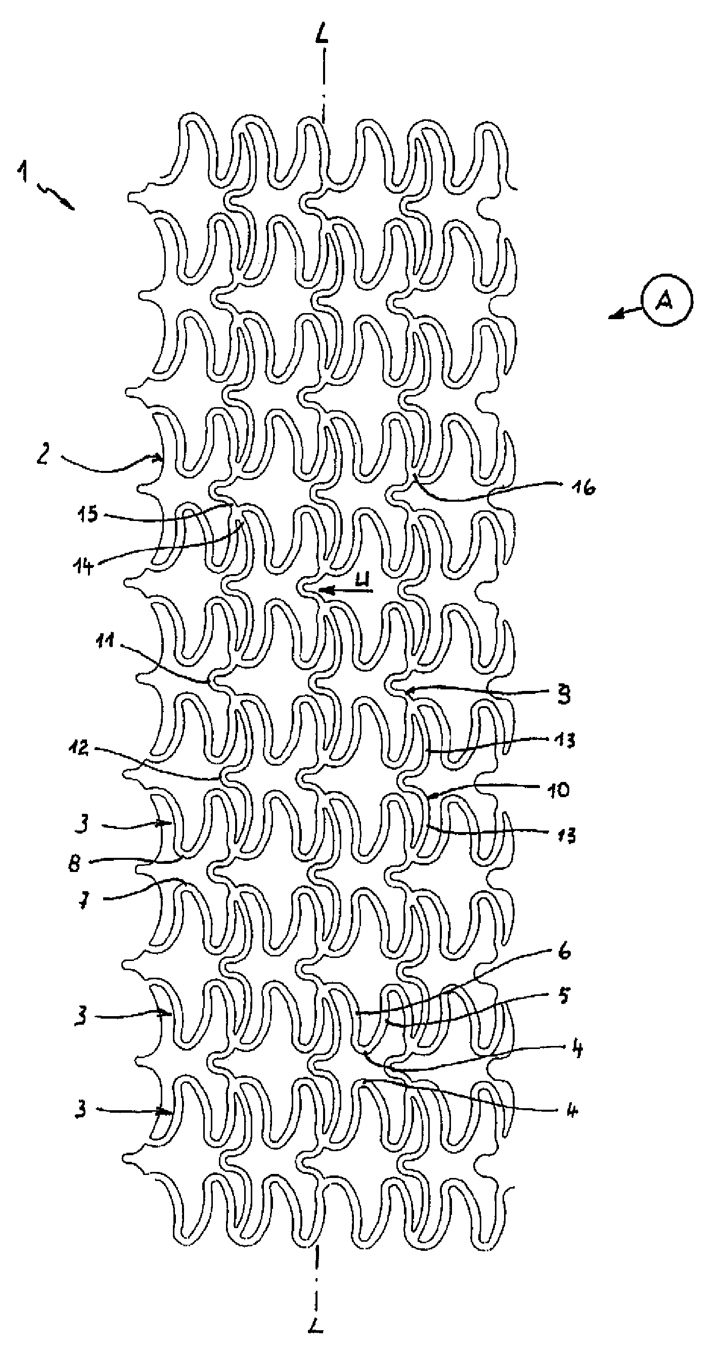
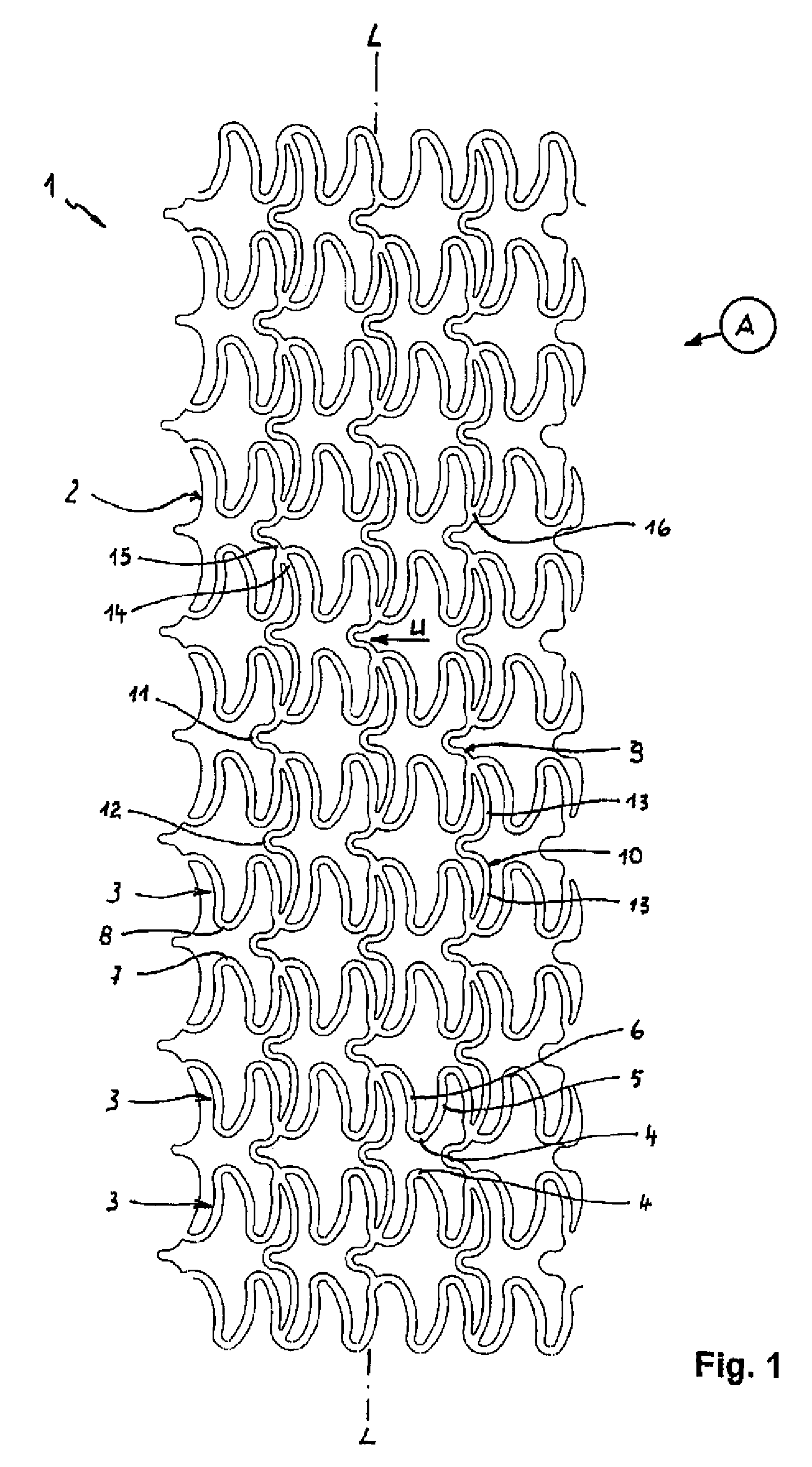
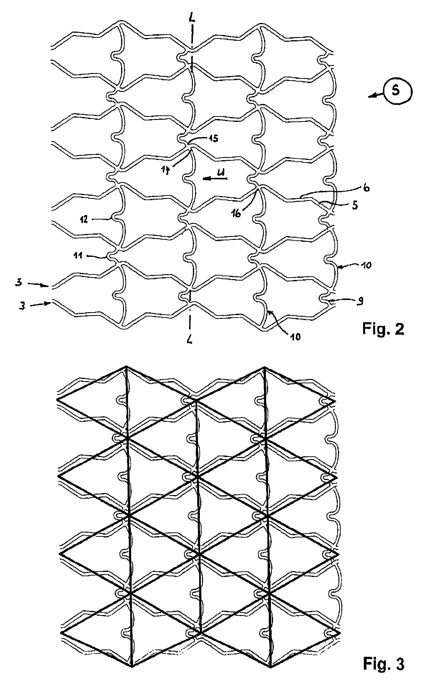
[0023]FIGS. 1 and 2 show each a developed view of the stent pattern of a stent 1 according to the invention. FIG. 1 shows the stent pattern of the stent 1 in initial state A after its manufacture. FIG. 2 represents the developed view of the stent pattern in expanded support state S.

[0024]The stent 1 is made of metal or plastic and includes a tubular support frame 2 of several ring segments 3 arranged successively behind one another. The illustrations of FIGS. 1 and 2 are not to scale. In particular FIG. 2 does not illustrate the total number of ring segments 3 of the stent 1 as in FIG. 1.

[0025]In the non-expanded initial state A, as shown in FIG. 1, the ring segments 3 have a wave-like configuration of struts 5, 6 which continuously adjoin one another via arcuate sections 4. Wave crests 7, on one hand, and wave valleys 8, on the other hand, of adjacent ring segments 3 oppose one another frontally. The rings segments 3 are interconnected by connectors 9, 10 which extend in the direct...


PUM


Abstract

A stent (1) is a vascular prosthesis for a constricted body vessel. The stent (1) includes a tubular support frame (2) of ring segments (3) arranged in axial succession and formed by struts (5, 6) which in initial state are joined continuously in a wave-like manner. Adjacent ring segments (3) are linked by differently long connectors (9, 10) with U-shaped compensating sections (11, 12). All connectors (9, 10) point in the same circumferential direction (U). Moreover, differently long connectors (9, 10) alternate in circumferential direction (U) as well as in longitudinal stent axis (L).

Description

CROSS-REFERENCES TO RELATED APPLICATIONS[0001]This application is the National Stage of prior filed copending PCT International application no. PCT / DE2004 / 002253, filed Oct. 11, 2004, which designated the United States and has been published but not in English as International Publication No. WO 2005 / 046522, and which claims the priority of German Patent Application, Ser. No. 103 52 874.1, filed Nov. 10, 2003, pursuant to 35 U.S.C. 119(a)-(d).BACKGROUND OF THE INVENTION[0002]The invention relates to a stent for treatment of stenoses.[0003]Stenoses are innate or acquired vessel blockages or constrictions of tubular body tubes, such as, for example, windpipe, bronchial tubes, esophagus, bile ducts, urinary passages, aorta, and coronary or other body vessels. Stenoses are oftentimes caused by tumors which exert pressure upon the body tubes. Stenoses can be opened by surgical and non-surgical procedures. Non-surgical procedures involve stents which are introduced into the vessel in the ...

Claims


Application Information

Patent Timeline
Patent Type & Authority Patents(United States)
IPC IPC(8): A61F2/06A61F2/91A61F2/915
CPCA61F2/91A61F2/915A61F2002/91541A61F2230/0054A61F2002/91566A61F2002/91583A61F2002/91558A61F2/07A61F2/89A61F2/90A61F2/82
Inventor NISSL, THOMAS
Owner QUALIMED INNOVATIVE MEDIZINPROD
Why Eureka
Try Eureka