Wireless charging circuit, system and method and electronic equipment

A wireless charging and circuit technology, applied in battery circuit devices, circuit devices, conversion equipment without intermediate conversion to AC, etc., can solve the problems of low charging efficiency and low charging safety.

Inactive Publication Date: 2018-06-29
MEIZU TECH CO LTD
View PDF8 Cites 3 Cited by
  • Summary
  • Abstract
  • Description
  • Claims
  • Application Information

AI Technical Summary

Problems solved by technology

[0006] Embodiments of the present invention provide a wireless charging circuit, system, method and electronic equipment to solve the problems of low charging efficiency and low charging safety in existing wireless charging circuits

Method used


Image

  • Wireless charging circuit, system and method and electronic equipment
  • Wireless charging circuit, system and method and electronic equipment
  • Wireless charging circuit, system and method and electronic equipment

Examples


Embodiment 1

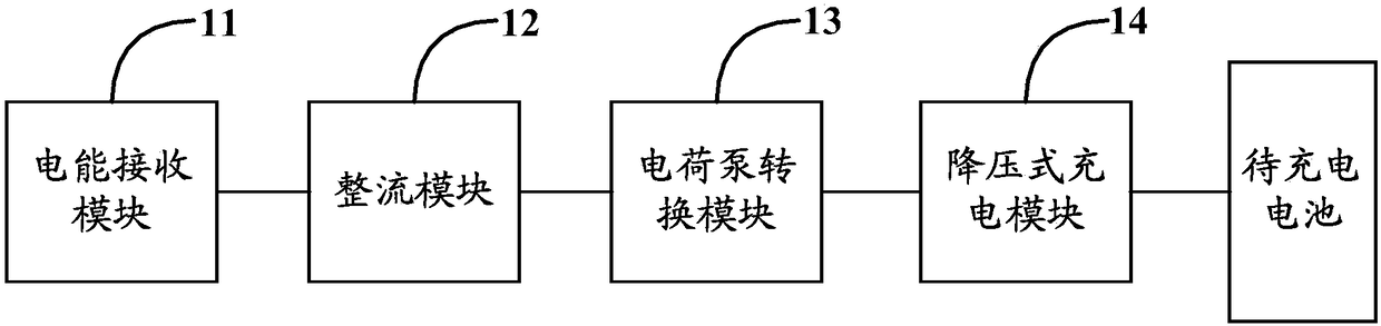
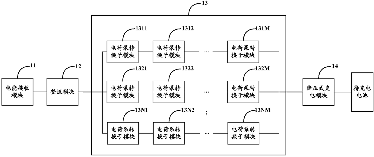
[0062] In order to solve the problems of low charging efficiency and low charging safety in existing wireless charging circuits, Embodiment 1 of the present invention provides a wireless charging circuit. Wherein, the wireless charging circuit can usually be set in a corresponding terminal device, such as a mobile phone, a tablet computer, a smart watch, a camera, etc., for when the terminal device establishes a coupling connection with a corresponding wireless adapter, The electric energy received from the wireless adapter is transmitted to the battery to be charged of the terminal device. Of course, the wireless charging circuit can also be used independently, which will not be described in detail. like figure 1 As shown in , it is a schematic circuit structure diagram of the first wireless charging circuit described in Embodiment 1 of the present invention. Specifically, such as figure 1 As shown, the first type of wireless charging circuit may include a power receiving m...

Embodiment 2

[0144] Based on the same inventive concept as the first embodiment of the present invention, the second embodiment of the present invention provides a wireless charging method, which can be applied to the wireless charging circuit described in the previous embodiment. For the same content, please refer to the first embodiment of the present invention. The relevant content of the present invention will not be described too much in the embodiment of the present invention. like Figure 11 As shown, it is a schematic flowchart of the wireless charging method described in Embodiment 2 of the present invention. Specifically, by Figure 11 It can be seen that the wireless charging method may include the following steps:

[0145] Step 1101: receiving the alternating current transmitted by the transmitting coil of the wireless adapter;

[0146] Step 1102: converting the alternating current into direct current;

[0147] Step 1103: step down and step up the direct current through the...


PUM


Abstract

The invention discloses a wireless charging circuit, system and method and electronic equipment. The wireless charging circuit comprises an electric energy receiving module, a rectifying module, a charge pump conversion module and a step-down charging module. The electric energy receiving module is used for receiving the alternating current transmitted by the electric energy transmitting module ofa wireless adapter. The rectifying module is used for converting the alternating current into direct current. The charge pump conversion module is used for performing voltage reduction and current enhancement on the direct current. The step-down charging module is used for adjusting the direct current after voltage reduction and current enhancement and transmitting the adjusted direct current toa battery to be charged. Compared with the circuits in the prior art, the charge pump conversion module is used as the conversion module of the wireless charging circuit, and the internal charge and discharge element is the capacitor rather than the inductor; besides, the current of the pre-circuit is enabled to be low and the coupling loss is enabled to be low by the charge pump conversion moduleso that the charging efficiency and the charging safety can be enhanced.

Description

[0001] This application claims the priority of the Chinese patent application with the application number 201720949202.X and the utility model name "a wireless charging circuit, system and electronic equipment" submitted to the China Patent Office on July 31, 2017, the entire contents of which are incorporated by reference incorporated in this application. technical field [0002] The invention relates to the technical field of charging, in particular to a wireless charging circuit, system, method and electronic equipment. Background technique [0003] As the functions of electronic devices become more and more powerful, the charging technology of electronic devices has also been continuously developed and improved. In order to improve the convenience of charging, wireless charging has gradually become a new charging trend. [0004] Specifically, there are very few terminal devices that can support wireless charging on the market, and the wireless charging circuit in these t...

Claims


Application Information

Patent Timeline
Patent Type & Authority Applications(China)
IPC IPC(8): H02J7/04H02J5/00H02M3/07
CPCH02J5/005H02J7/04H02M3/07H02M3/072Y02B40/00
Inventor 黄昌松陈林锋贾勇
Owner MEIZU TECH CO LTD
Why Eureka
Try Eureka